 I’ve successfully attached the router bracket I made to a virtual robot model in the programming software. I followed an example file provided by the software’s developers in Vienna, Austria. This was actually simpler than I thought, as I already had the design files for the bracket (that’s how I cut them out last week).
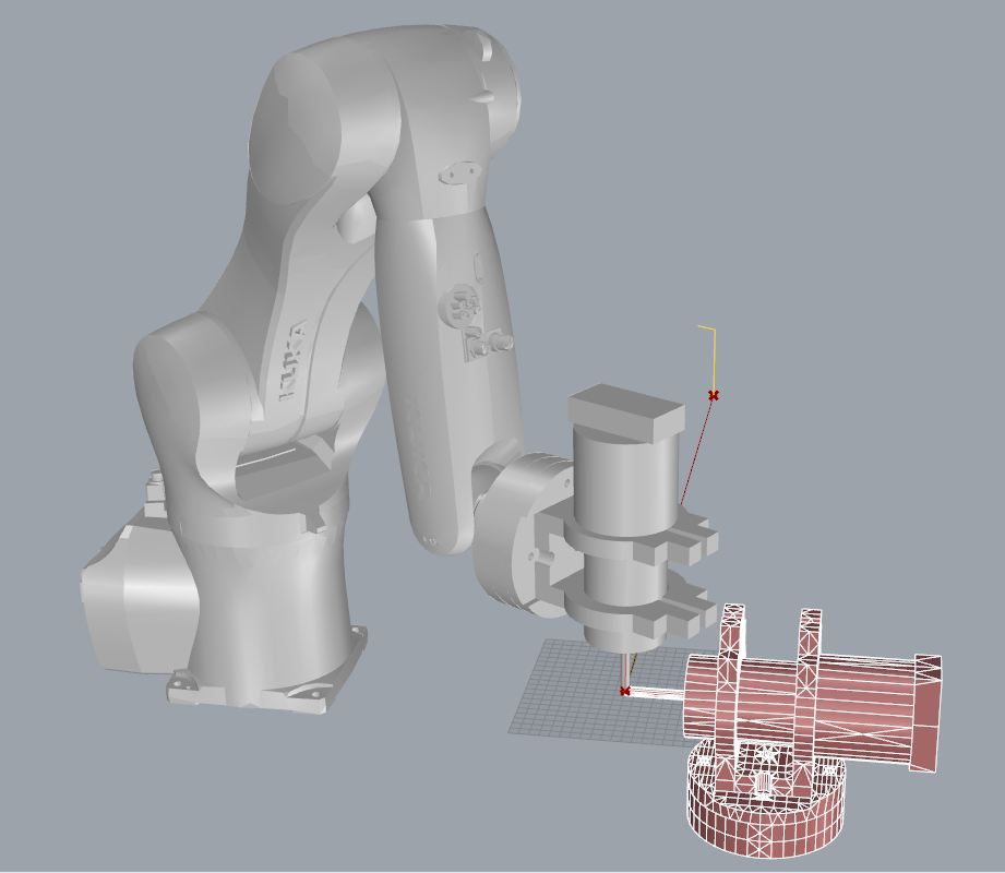
The robot in this picture is a different model than ours, but it serves to flesh out the concept and test the software to be sure I know what I’m doing. Eventually I’d like to have our robot/spindle model integrated into the software as a standard object; that will get rid of the ever-present red imported model in this image. (When I bring in my custom robot model, that will be in red as well)
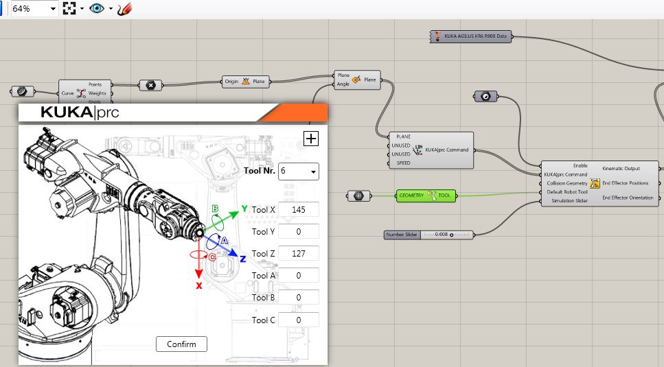 Standard CNC machines usually have 3 axes that run in a straight, linear fashion. That means you can manually jog the machine to wherever you need it, position the end of the milling bit on your raw material, press “zero-out” and you’re good to go. Not so here, the precise position of the end of the milling bit relative to the end of the robot arm needs to be measured and entered into the software.
These measurements may take a few days to dial in by making numerous test cuts, but foam is cheap, it doesn’t wear down the milling bits like wood or metal would do… Stay tuned for actual cutting of foam!