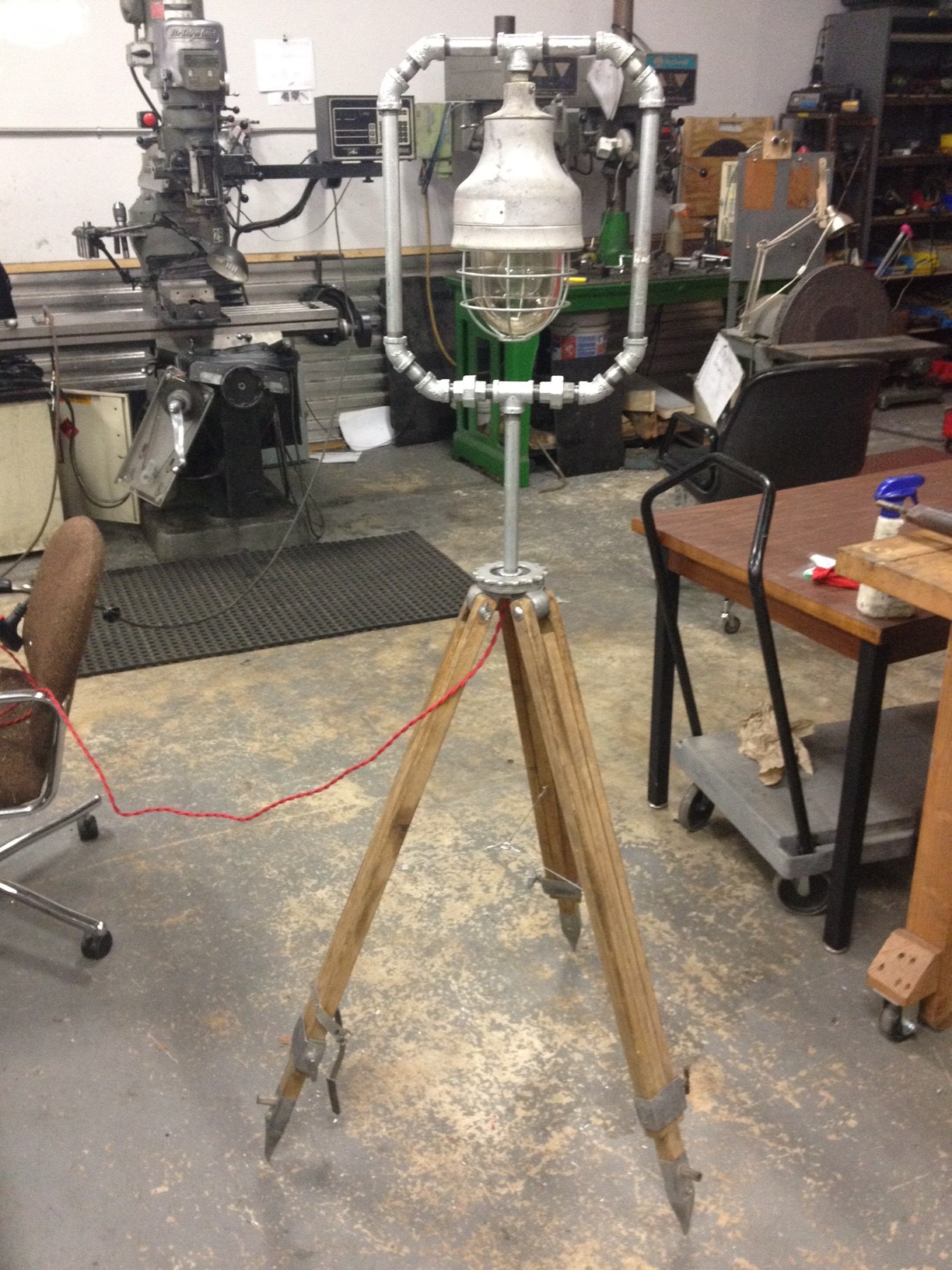
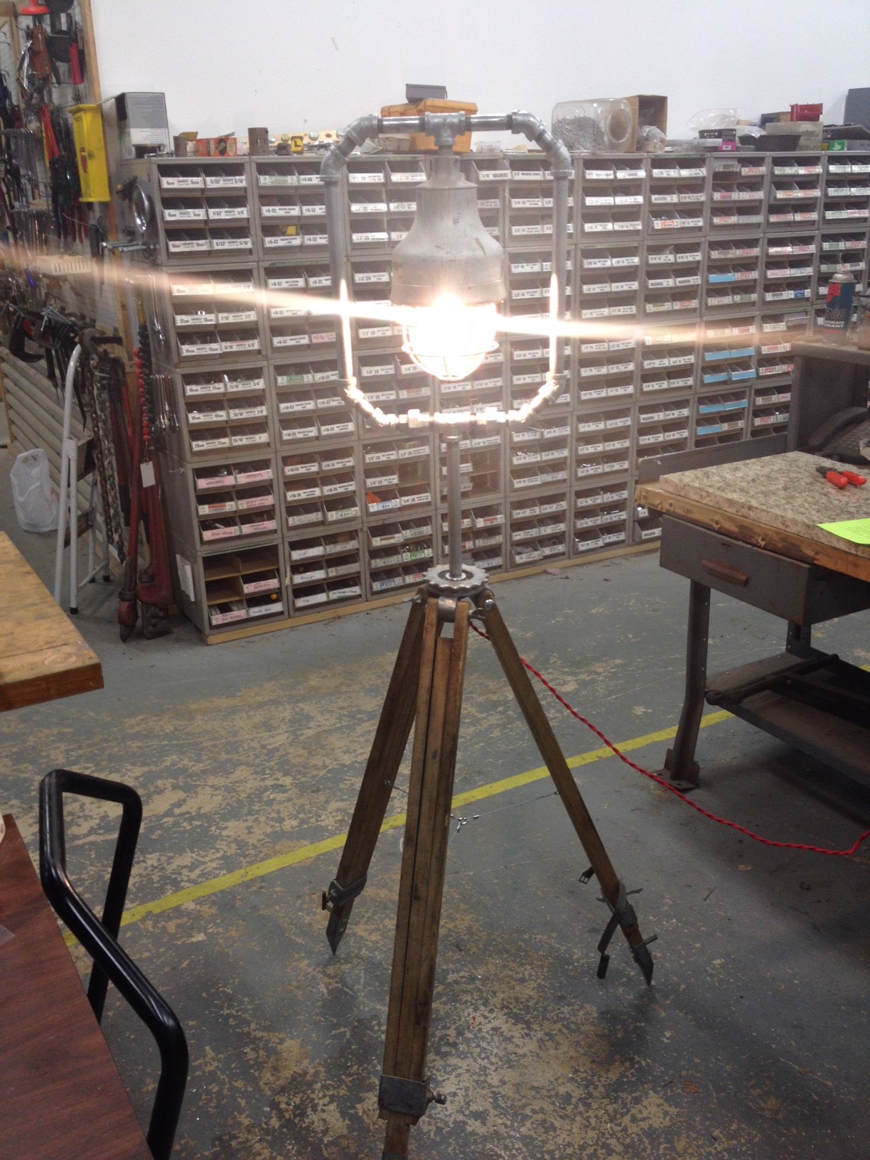
Joseph created a very unique lamp using an old surveyor’s tripod, blast proof industrial light, and galvanized pipe.

Be a part of a hacker/builder community where ideas are shared, innovation is fostered and the maker experience is hands-on.
Join us Tour the SpaceJoseph created a very unique lamp using an old surveyor’s tripod, blast proof industrial light, and galvanized pipe.
A student from a local university reached out to us earlier this year to create a light based object for a class project. I volunteered to help her and after many iterations, we decided to build a diffused RGB Lamp.
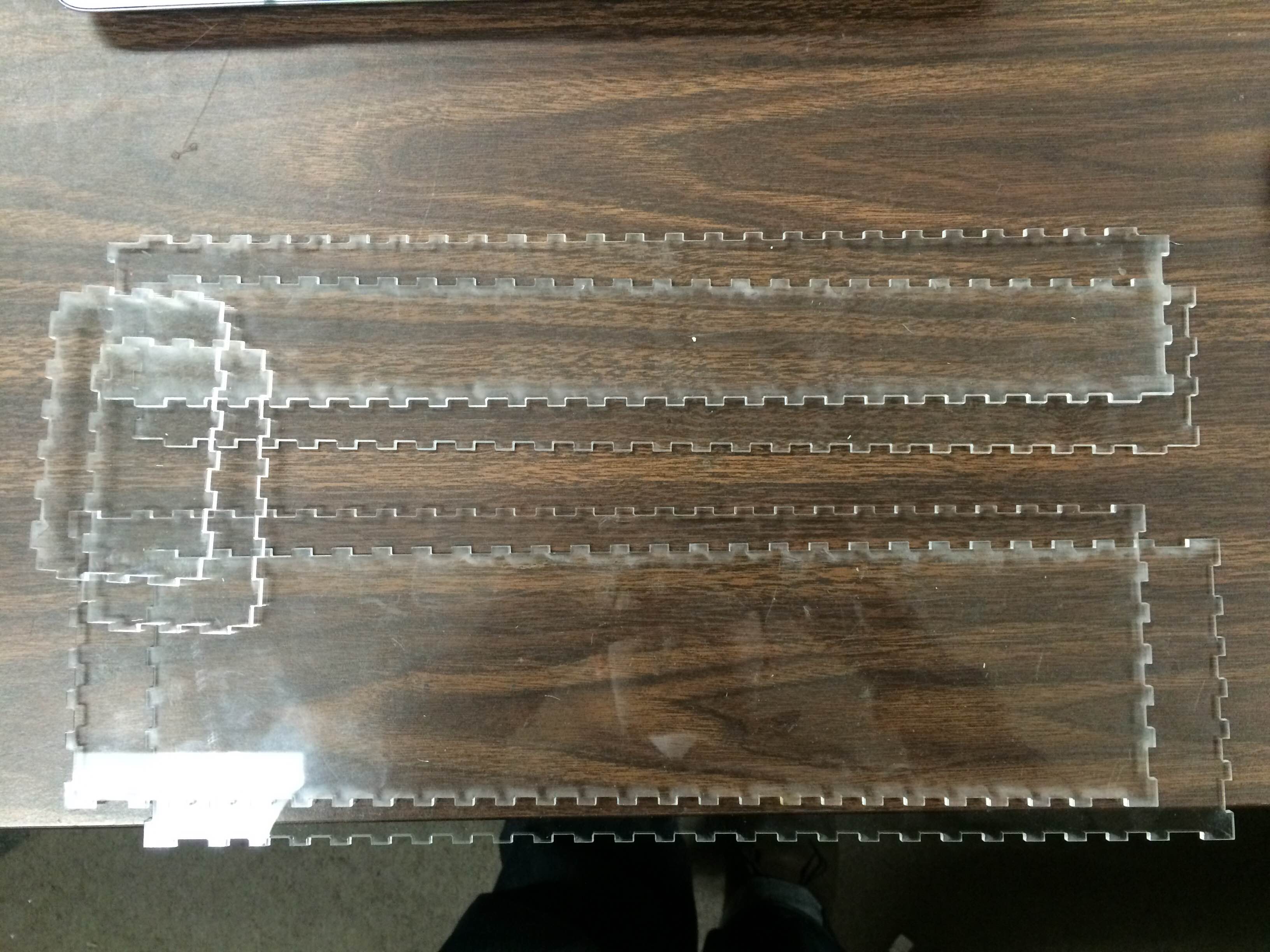
The finger-jointed acrylic body was designed using makercase.com and laser cut.
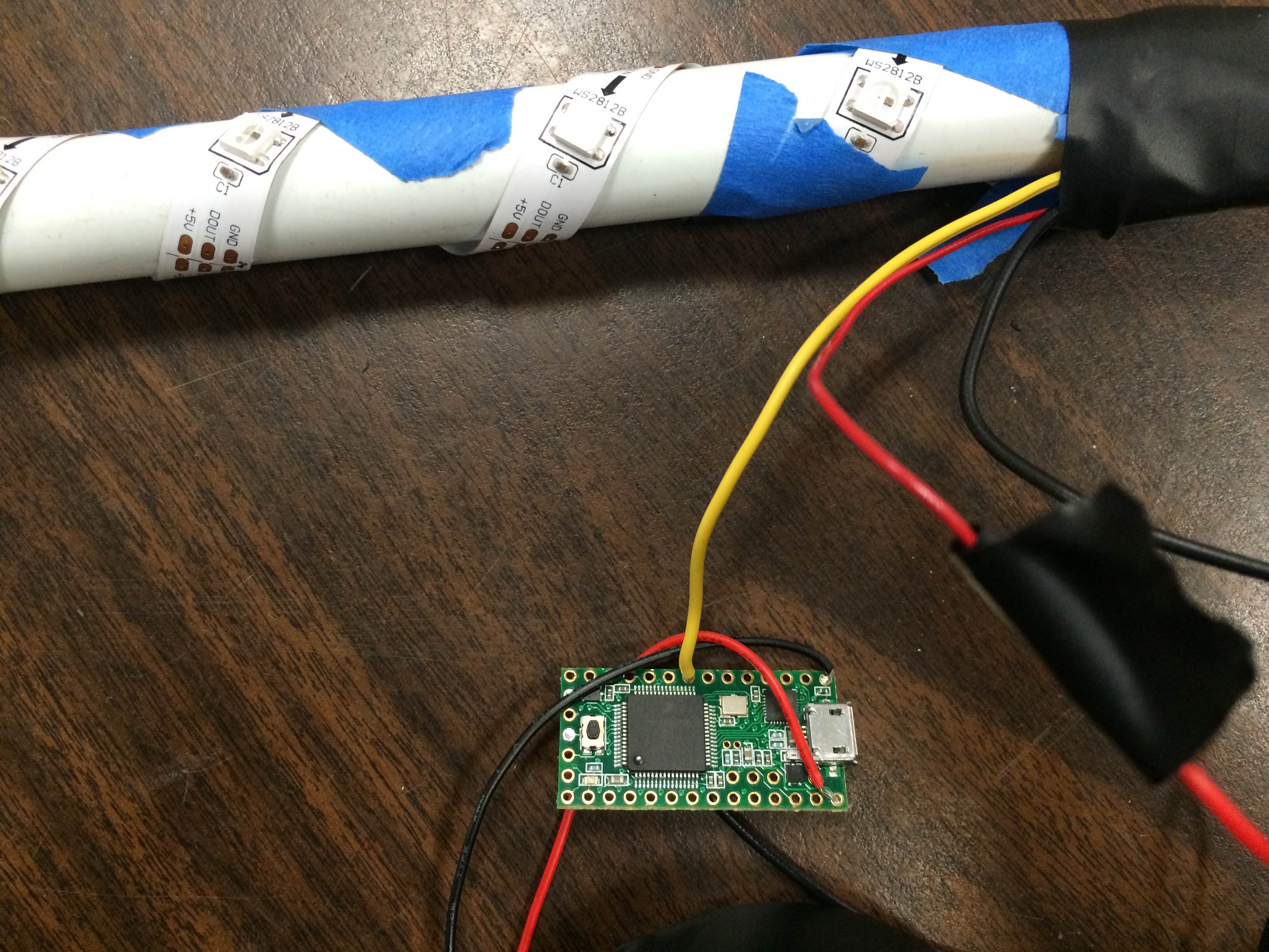
I used the addressable RGB LED strip from Adafruit, called Neopixels, to provide the lighting effects. The LED strip was wrapped around a PVC pipe in a spiral so it could provide light on all four (4) sides. The spiral spacing gets tighter near the top to either to vary the lamp density for a cool effect or I got lazy since this was done at 1AM on a Monday morning – I’ll let you decide.
![]()
A Teensy 3.1 controls the strip using the Adafruit Neopixel library. Two (2) sets of three (3) rechargable NiMH batteries were used. At full charge, a bank provided 3.82 Volts. While the micro controller was running happily, the LEDs were noticeably dim. While the vellum paper diffused the lights effectively, the distance to the acrylic was relatively small, so brighter LEDs would have decreased the desired gradient effect anyway.
We cut the vinyl logo and border using a Silhouette CAMEO. The final design had to be mirrored since it would be adhered to the inside of the acrylic case using transfer paper. The text on the top did not cut very well so we’ll re-cut that bit with more optimized fonts. After seeing the results, I think I’ll create a lamp for myself as well.

All previous updates can be found here.
As I mentioned last week, the project to build a dynamic scuplture using 480 balls is now called Douglas. What does Douglas stand for, you ask? It is Dynamic Objects Under Gravity Linearly Accelerating in Space. It took 2 minutes to define what the acronym means – perhaps we should have taken longer. Yes, in true Milwaukee Makerspace fashion, we found an acronym first, and then found a definition for it. In addition to this huge accomplishment, we made some other progress too!
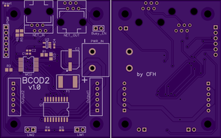
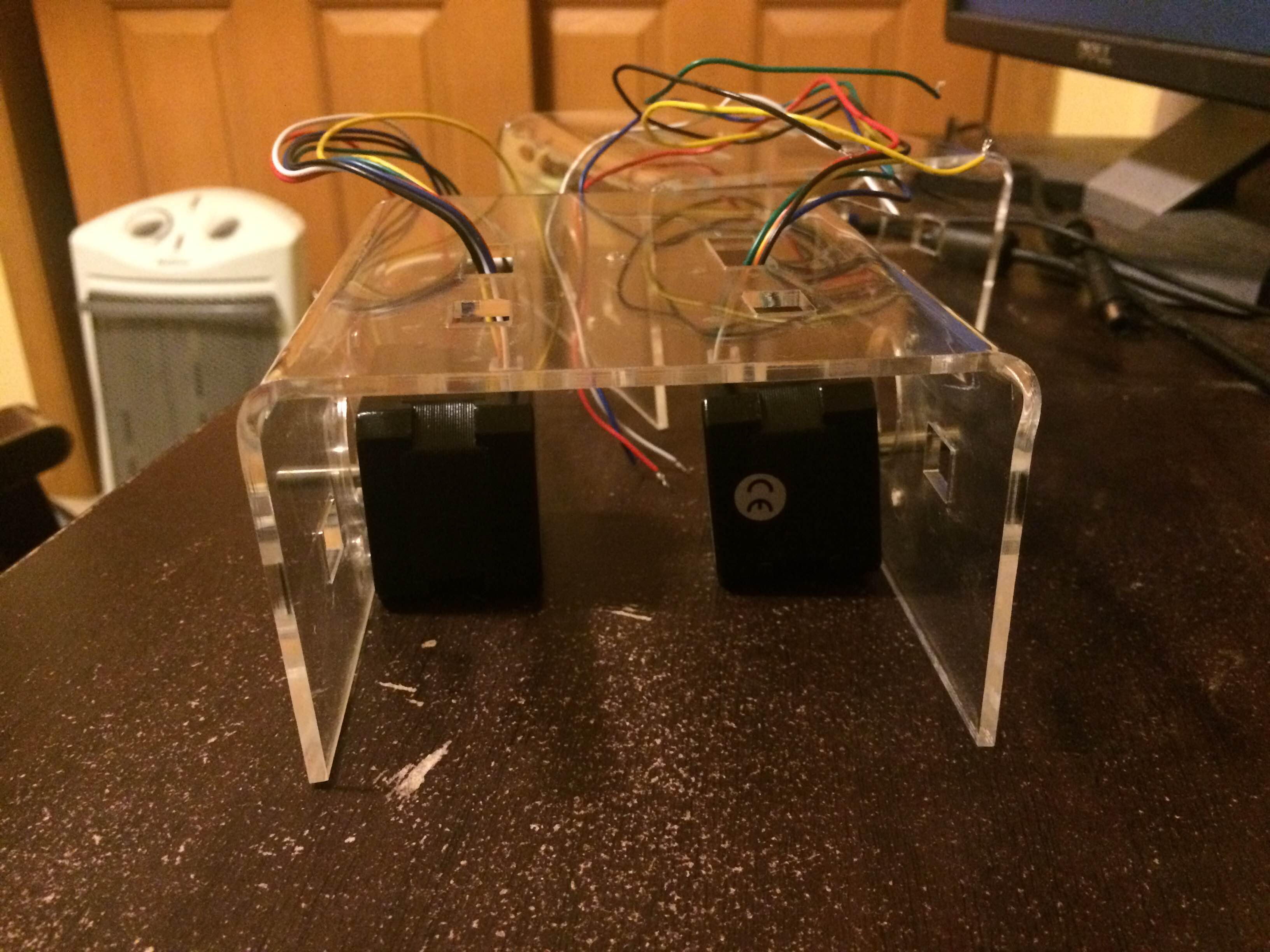
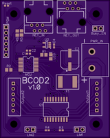
Chris sent the slave controller boards pictured below to OSHPark for fabrication. Six (6) boards were ordered as a proof of concept. They should be here by the 30th.
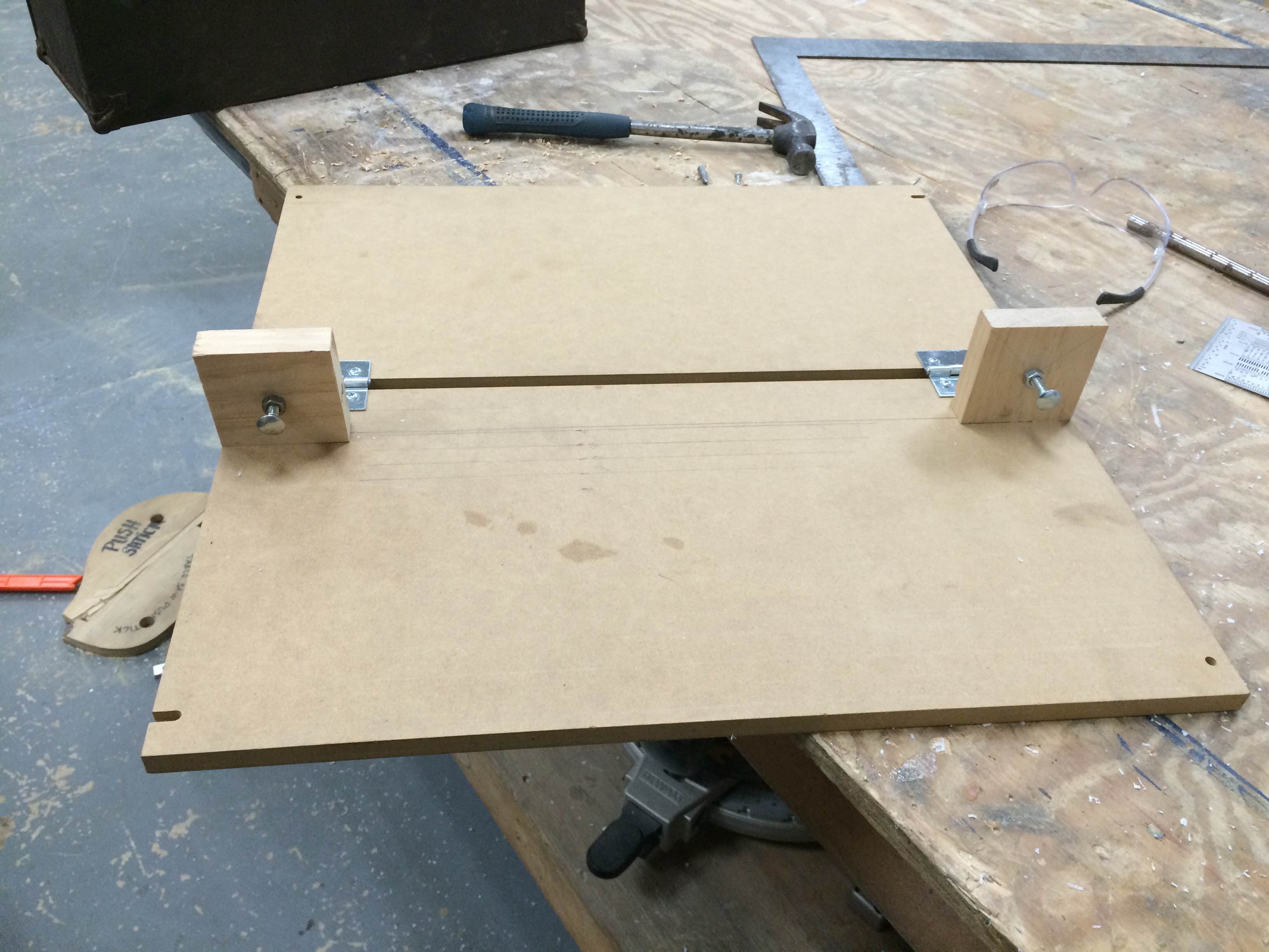
I made a bending jig to get more repeatable acrylic motor mounts pictured in the last update. It’s made out of two 1/2 inch pieces of mdf connected together with a hinge. The two adjustable screws determine the bending angle. Currently, they are set for 90 degrees. But bent acrylic usually “snaps back” as it cools, so it will have to be bent more that the desired final angle. Further experimentation will yield that angle and the adjustable screws will serve as stops for the mdf board. In the picture below, you can see parallel pencil lines indicating depth of the bent “arm” of the mount. The acrylic will butt up again a fence to be placed along one of those lines.

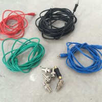
One of the goals of this project is to get kids interested in making by actually building parts of installation. This past Thursday, kids actually cut, stripped, and crimped connectors for RJ11 cables! These four (4) conductor “telephone” cables will be used to communicate between the control boards. I hope to have pictures of this awesome event in the next update.
The first update can be found here.
The dynamic sculpture is affectionately called “Douglas” till we come up with a better name. Lance, Chris, and I have been working on different pieces of the project concurrently.
Chris has been designing the slave controller PCB. Each PCB will have a PIC micro controller, which will drive (2) stepper motor through a ULN2803 chip. The PIC controllers will communicate to a chipKIT™ WiFire over SPI. The WiFire has built in SD Card and WiFi. Since Douglas will be hung in an atrium, this allows us to send new animations wirelessly to a SD Card.
Lance has been working on the PIC firmware and the communication protocol. The firmware interprets the “G-Code” like commands and drives each stepper at the specified acceleration and velocity.
I have been designing the motor mount and frame in Inventor. A few pics below.
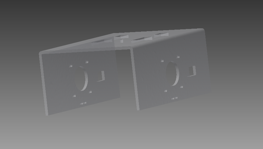

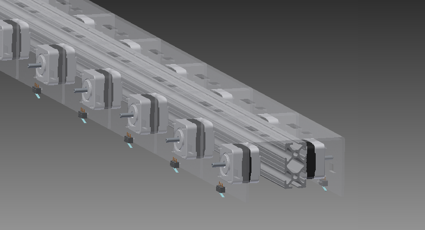
The bent acrylic mount will be mounted on aluminum extrusions. The limit switch has been integrated into the mount as well. I built the first prototype a couple of days ago.
Next, I will create a bending jig to replicate the mount accurately. Additionally, we will be doing some measurements to figure out power consumption. Currently, it looks like we will need two dedicated 120V, 20 amps circuits. We would like to do some real world combined power consumption tests to see if we can lower that requirement.
This weekend, I helped decorate for a Halloween Party at my sister’s house. There’s an odd hallway that connects their main large public room to the rest of the house. It’s used for storage, and has shelves on both sides.
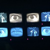
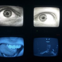
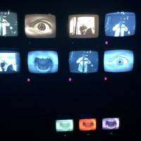
This year, I decided to decorate that area by creating a video wall effect. Something like a Television Control Room of Terror!
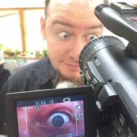
To start with, I simply filmed my brother-in-law with a video camera – only from WAY TOO CLOSE! I shot macro video of his eye and mouth. Then I edited the footage to create a custom looping DVD.
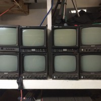
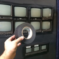
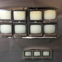
In the hallway, I set up multiple monitors. These are old monochrome standard definition monitors that were on their way to the recycling center. They were professional monitors, which means that they can pass a video signal through from one monitor to another, making it easy to daisy chain several monitors.
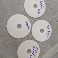
Next to the monitors, I set up three DVD players (including one car DVD player – hey I use what I got!) to play the three different custom DVDs – Right Eye, Left Eye, and Mouth. Each of the three videos is a different length, so they will continue to drift out of sync. That way, as they loop, the visuals are a continuingly changing experience through the whole evening.
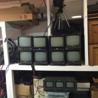
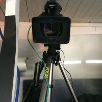
Above the monitors, I set up a video camera on a tripod and fed it to some of the monitors. That way, when party-goers look at the monitor, they also see themselves. Having feedback on some of the monitors adds a sense of interactivity to the project.
After the monitors and DVD players were all set up, I covered the rest of the shelving with black paper. In a dark hallway, lit only be black lights, it’s a great effect of creepy images floating in the hall.
If you want more details on this project, I made a full step-by-step write-up on Instructables.