Douglas – Update 3

All previous updates can be found here

As I mentioned last week, the project to build a dynamic scuplture using 480 balls is now called Douglas. What does Douglas stand for, you ask? It is Dynamic Objects Under Gravity Linearly Accelerating in Space. It took 2 minutes to define what the acronym means – perhaps we should have taken longer. Yes, in true Milwaukee Makerspace fashion, we found an acronym first, and then found a definition for it. In addition to this huge accomplishment, we made some other progress too!

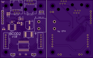
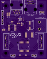
Chris sent the slave controller boards pictured below to OSHPark for fabrication. Six (6) boards were ordered as a proof of concept. They should be here by the 30th.


board


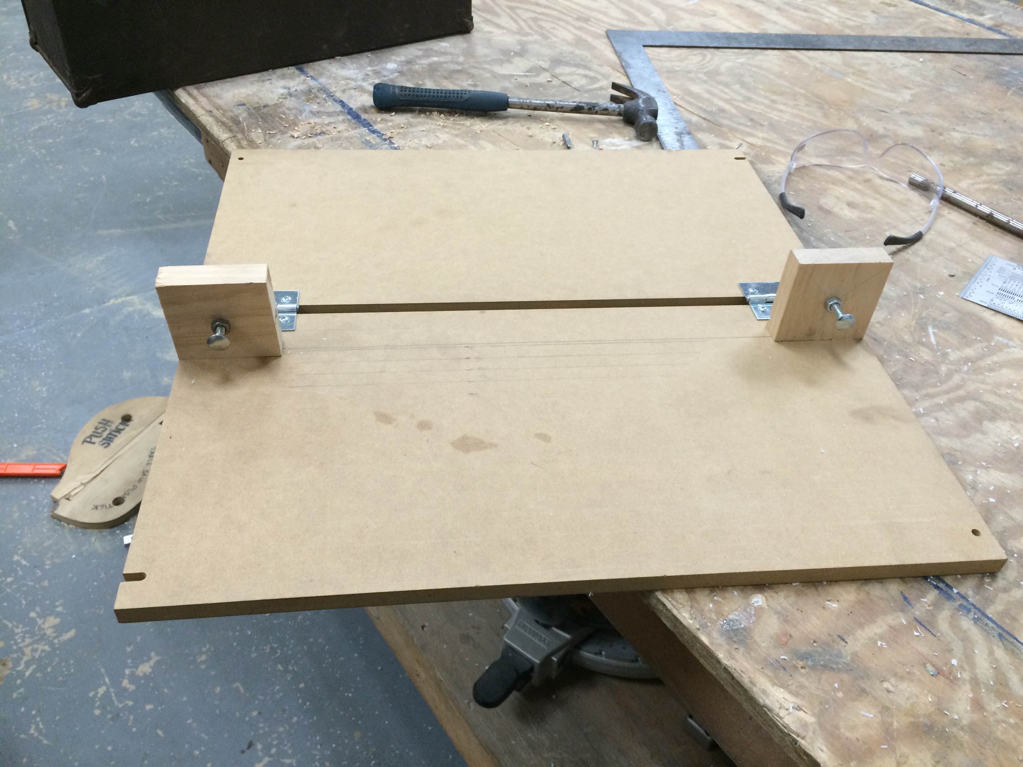
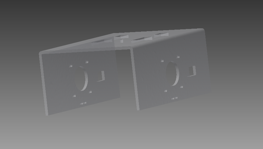
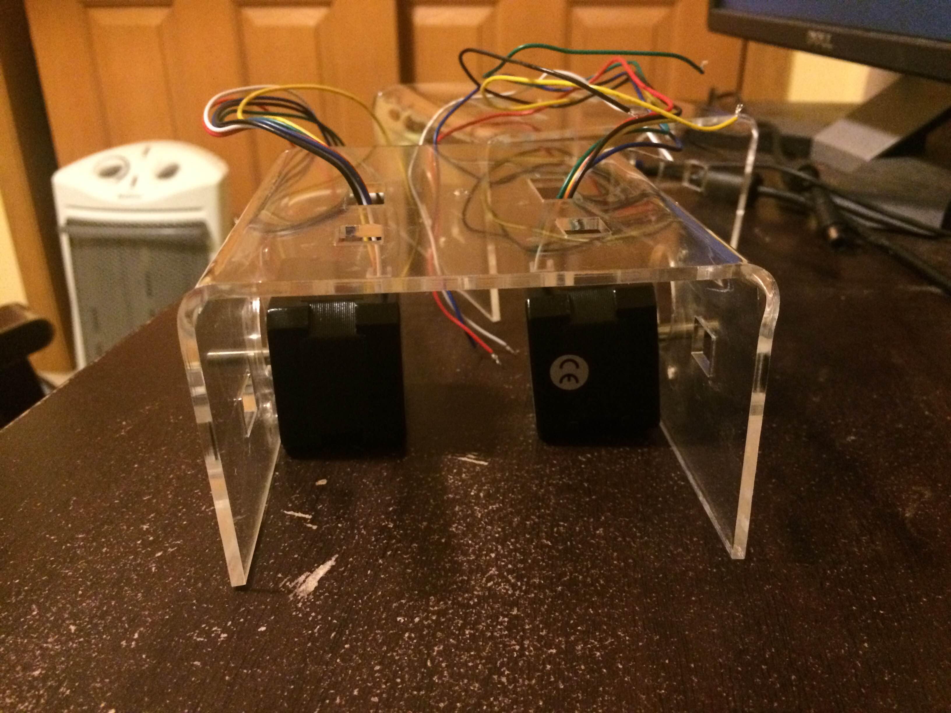
I made a bending jig to get more repeatable acrylic motor mounts pictured in the last update. It’s made out of two 1/2 inch pieces of mdf connected together with a hinge. The two adjustable screws determine the bending angle. Currently, they are set for 90 degrees. But bent acrylic usually “snaps back” as it cools, so it will have to be bent more that the desired final angle. Further experimentation will yield that angle and the adjustable screws will serve as stops for the mdf board. In the picture below, you can see parallel pencil lines indicating depth of the bent “arm” of the mount. The acrylic will butt up again a fence to be placed along one of those lines.


IMG_0803

IMG_0802


One of the goals of this project is to get kids interested in making by actually building parts of installation. This past Thursday, kids actually cut, stripped, and crimped connectors for RJ11 cables! These four (4) conductor “telephone” cables will be used to communicate between the control boards. I hope to have pictures of this awesome event in the next update.

Dynamic Sculpture – Update 2

The first update can be found here.

The dynamic sculpture is affectionately called “Douglas” till we come up with a better name. Lance, Chris, and I have been working on different pieces of the project concurrently.

Chris has been designing the slave controller PCB. Each PCB will have a PIC micro controller, which will drive (2) stepper motor through a ULN2803 chip. The PIC controllers will communicate to a  chipKIT™ WiFire over SPI. The WiFire has built in SD Card and WiFi. Since Douglas will be hung in an atrium, this allows us to send new animations wirelessly to a SD Card.

Lance has been working on the PIC firmware and the communication protocol. The firmware interprets the “G-Code” like commands and drives each stepper at the specified acceleration and velocity.

I have been designing the motor mount and frame in Inventor. A few pics below.

mount_1 mount_2 mount_3

The bent acrylic mount will be mounted on aluminum extrusions. The limit switch has been integrated into the mount as well. I built the first prototype a couple of days ago.

IMG_0788

Next, I will create a bending jig to replicate the mount accurately. Additionally, we will be doing some measurements to figure out power consumption. Currently, it looks like we will need two dedicated 120V, 20 amps circuits. We would like to do some real world combined power consumption tests to see if we can lower that requirement.

Dynamic Sculpture – Update 1

I am collaborating with the Betty Brinn Children’s museum to create something similar to this.

This sculpture has 844 balls hanging from strings wound around a pulley on a DC motor shaft. Ours will feature somewhere between 320 to 500 balls. I am currently working on a prototype to test and qualify different electronic and control platforms. It’s made out of 40mm x 40mm aluminum extrusion, laser cut wood motor mounts, 5V steppers, and ULN2003 based stepper drivers. I have been using an Arduino mega for now to test the motor and drivers.

IMG_0708

IMG_0709

The next step is to write software to create “voxels” with instructions akin to G-code. Additional software will be necessary to simulate the animation. G-code like instructions will be used by microcontrollers to control steppers in order to create an animation.