Fun With Fractals

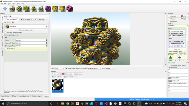
Over the past few months I have been playing with 3D fractals to create slip cast pottery.  I found a free program called Mandelbulber 3D and you know me, If it’s free I’ll take 3.  It’s shocking to me the availability of free software like this.  Right now I am just scraping the surface on what the software can do but I have a few examples of shapes made in the software posted on Thingiverse.

https://www.thingiverse.com/thing:5138435

Creating the fractals with the Mandelbulber is fairly straight forward.  Just experiment with varying a few values and click render.  The hard part is getting the shape to be cast-able with out having to make a 27 part mold.  A few weeks ago I pulled the first cast from my first successful mold.  This is part fractal and part Fusion.  The foot of the cup is part of the fractal pattern and the body of the cup is a shape designed in Fusion 360.  Although the final product warped in the kiln I think it was a good proof of concept.

After the shape is created digitally you have to make it physical.  My go to method is usually my 3D printer.  The constraints that make a part easy to 3d print without supports are similar to the  constraints that make a part easy to remove from a mold.  To make the slip cast mold I don’t print the cup but a plastic mold of the cup, there are two reasons for this.  First if you are going to make lots of slip casts you are going to need more than one mold.  Because of the time it takes to cast each cup you will need to pour several mold each day.  Second with a hard plastic mold you can make a soft silicone part.  This saves me from making a large silicone Mother Mold of my 3D printed mold.  My Mother Mold is half of the 3D printed mold with the full silicone cast part inside.  It’s worth noting that there is 15-18 percent of shrinkage from pour to final firing so you will need to scale up your prints to an almost comical size. 

(photo coming soon)…

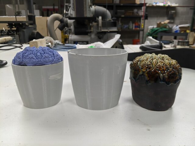
On a side note I did some experimenting is soaking silicone parts in IPA to expand them.  This is a fun exercise if you have never done it.  To expand a part just place it in a container of IPA for several hours.  I let one part sit over night and go about the amount of growth I was looking for to but the part shrinks down slowly when removed from the IPA and the growth amount is not very predictable.  Below you can see an example of how much larger the part grew and the final fired piece from this process.

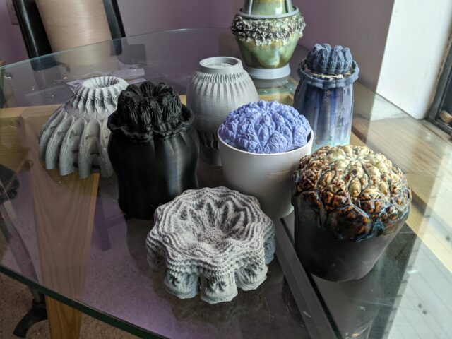
I am in the process of printing my molds right now so tonight at the open meeting I might have printed molds to show.  I also have other shapes to pass around.


Son of MegaMax Lives!

MegaMax was a great 3D printer, but it was time for some changes.  He was difficult to transport because the electronics were in a separate housing with many cables to disconnect and reconnect, barely fit through doorways, and required a positively gargantuan enclosure to keep the temperature up to control ABS delamination.  Though it hurt to do it, I tore him apart and did a complete redesign/build into a form that is more like what I would have done had I known anything at all about 3D printing when I started building MegaMax.

I reused what I could including a lot of the 8020 extrusions in the frame, the Z axis screw assemblies and drive belt, and the X and Z axis motors.

Changes include:

  • ball screw drive Y axis with high torque motor- precise but noisy
  • linear guides in X and Y axes instead of 1/2″ round guide rails and linear bearings
  • SmoothieBoard controller instead of Arduino/RAMPS
  • BullDog XL extruder and E3D v6 hot end
  • RepRapDiscount graphic LCD control panel
  • narrower frame design without giving up print volume- easier fit through doorways!
  • polycarbonate panels to enclose the print area yet provide a clear view of the print
  • electronics in a drawer for easy service and transport and neater appearance
  • DSP motor drivers and 32V power supplies for X and Y axes
  • Liberal use of screw terminals to make servicing easier
  • Modular X and Y axes that can be removed for service and replaced in minutes.

SoM will be making his public debut at the Milwaukee Makerspace very soon…

Son of MegaMax electronics drawer

Son of MegaMax electronics drawer

Side view of Son of MegaMax

Side view of Son of MegaMax


Douglas – Update 3

All previous updates can be found here

As I mentioned last week, the project to build a dynamic scuplture using 480 balls is now called Douglas. What does Douglas stand for, you ask? It is Dynamic Objects Under Gravity Linearly Accelerating in Space. It took 2 minutes to define what the acronym means – perhaps we should have taken longer. Yes, in true Milwaukee Makerspace fashion, we found an acronym first, and then found a definition for it. In addition to this huge accomplishment, we made some other progress too!

Chris sent the slave controller boards pictured below to OSHPark for fabrication. Six (6) boards were ordered as a proof of concept. They should be here by the 30th.


board


I made a bending jig to get more repeatable acrylic motor mounts pictured in the last update. It’s made out of two 1/2 inch pieces of mdf connected together with a hinge. The two adjustable screws determine the bending angle. Currently, they are set for 90 degrees. But bent acrylic usually “snaps back” as it cools, so it will have to be bent more that the desired final angle. Further experimentation will yield that angle and the adjustable screws will serve as stops for the mdf board. In the picture below, you can see parallel pencil lines indicating depth of the bent “arm” of the mount. The acrylic will butt up again a fence to be placed along one of those lines.


IMG_0803

IMG_0802


One of the goals of this project is to get kids interested in making by actually building parts of installation. This past Thursday, kids actually cut, stripped, and crimped connectors for RJ11 cables! These four (4) conductor “telephone” cables will be used to communicate between the control boards. I hope to have pictures of this awesome event in the next update.

Dynamic Sculpture – Update 2

The first update can be found here.

The dynamic sculpture is affectionately called “Douglas” till we come up with a better name. Lance, Chris, and I have been working on different pieces of the project concurrently.

Chris has been designing the slave controller PCB. Each PCB will have a PIC micro controller, which will drive (2) stepper motor through a ULN2803 chip. The PIC controllers will communicate to a  chipKIT™ WiFire over SPI. The WiFire has built in SD Card and WiFi. Since Douglas will be hung in an atrium, this allows us to send new animations wirelessly to a SD Card.

Lance has been working on the PIC firmware and the communication protocol. The firmware interprets the “G-Code” like commands and drives each stepper at the specified acceleration and velocity.

I have been designing the motor mount and frame in Inventor. A few pics below.

mount_1 mount_2 mount_3

The bent acrylic mount will be mounted on aluminum extrusions. The limit switch has been integrated into the mount as well. I built the first prototype a couple of days ago.

IMG_0788

Next, I will create a bending jig to replicate the mount accurately. Additionally, we will be doing some measurements to figure out power consumption. Currently, it looks like we will need two dedicated 120V, 20 amps circuits. We would like to do some real world combined power consumption tests to see if we can lower that requirement.

Dynamic Sculpture – Update 1

I am collaborating with the Betty Brinn Children’s museum to create something similar to this.

This sculpture has 844 balls hanging from strings wound around a pulley on a DC motor shaft. Ours will feature somewhere between 320 to 500 balls. I am currently working on a prototype to test and qualify different electronic and control platforms. It’s made out of 40mm x 40mm aluminum extrusion, laser cut wood motor mounts, 5V steppers, and ULN2003 based stepper drivers. I have been using an Arduino mega for now to test the motor and drivers.

IMG_0708

IMG_0709

The next step is to write software to create “voxels” with instructions akin to G-code. Additional software will be necessary to simulate the animation. G-code like instructions will be used by microcontrollers to control steppers in order to create an animation.