For years I have dreamed of a fast way to prototype PCB for projects I am designing.
20 years ago I was using rub on drafting tape and stencils – slow and spotty results.
I tried to modify a plotter to plot resist directly to a PCB – no luck.
Magic markers – I’m no artist.
5 years ago I hacked a laminate router by tapping into the stepper controllers and adding a better Z axis – It can rout boards ok, but takes some tweaking. It only does fairly wide traces. But its great at drilling holes!
2 years ago I tried the inkjet printing systems – lots of smeared wet ink and poor registration, not very effective.
I opened up a laser printer and tried to get a board to go through it – almost worked, but the fuser was to narrow to take the board.
Although I haven’t found a fast system yet, I get by with the PNP Blue material and a good laminator. Although I am regularly disappointed when dust, not quite clean boards, minor wrinkles and other issues leave gaps in traces that need touching up.
Which brings us to the latest attempt:
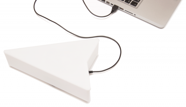
Now that the maker space has a small laser cutter I am trying to find something I can coat a board with and either burn away or melt onto the board to act as an etch resist.
Early attempts with paint had moderate results – our laser cutters on only 25W so it didn’t burn it cleanly. I have heard that using flat black paint and a more powerful laser works.
Paste wax and markup fluid weren’t dark enough for the laser to vaporize (thinking of trying black crayons)
The latest attempt uses laser printer toner (just like the PNP only skipping the printing and iron on steps.)
The problem is how to get an even coat on a board without it blowing around. Static electricity has potential (just like what they do inside a laser printer) but I don’t like the idea of a 5KV power supply exposed and handling powered toner is an automatic mess.
So for the first attempt I mixed the toner with rubbing alcohol (30% water).
Messy stuff!
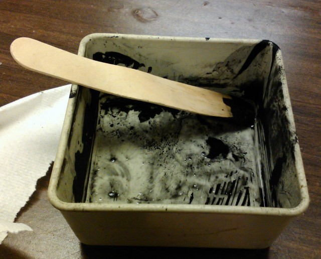
I painted it on with the tongue depressor but it seemed to coat evenly and took only a few minutes to dry:
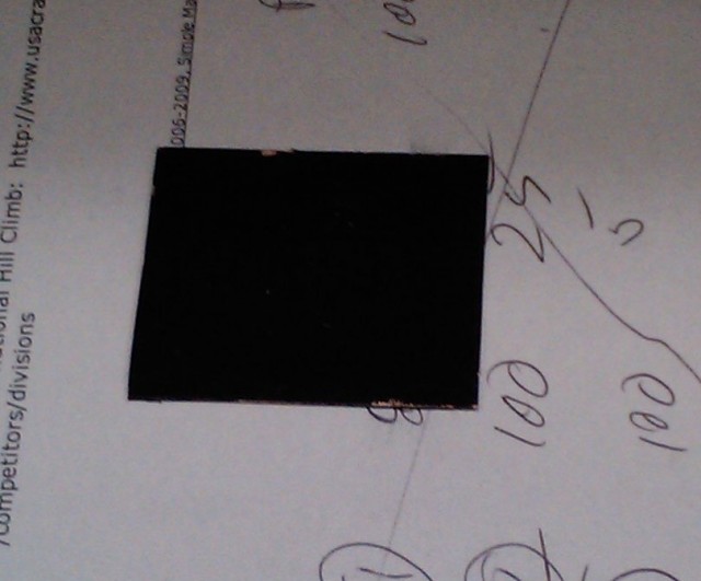
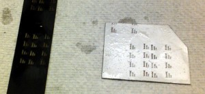
It mixes well and paints on fairly easily, here are some sample prints I did at various power and speed settings. I cleaned the board fairly aggressively with paper towel and rubbing alcohol.
None are quite clean enough to become PCBs but they are getting close.
Although the toner paint looked dry, it may still have had some water in it. I plan on trying a batch with denatured alcohol (100% – no water) and see if it works better.
2/16/2012
Updated progress
I have been trying a number of materials and methods to make my fast turn circuit boards.
I’ve decided that last toner is too messy and there are too many variables to create a repeatable process. So now I’m trying various other masking materials:
Black and white spray paint – it works ok, but the ash left behind by the laser resists the etchant and leaves you with a poor etch.
I also tried tape: Painters tape, electrical tape, clear and brown box tape. The masking tape worked ok until the etch was slow and the tape started to dissolve.
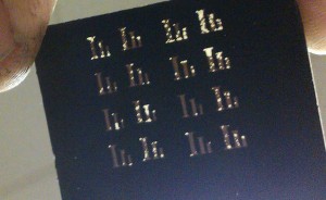
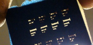
I held a few of the boards up to the light so you can see how it etched:
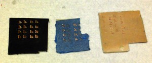
One of the other members of the space found someone who had made the black paint work. The process is to do 2 passes with the laser – the first burns off the paint, the second burns off the ash! Then you wipe the board down with rubbing alcohol to clean off any residue. Here is a set of 3 projects I lasered and etched at once:
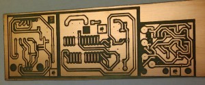
This board turned out rather well, I had some trouble with the etchant taking for ever so lost some of the detail on the lettering, but the boards came out nicely. I should get even better results on the next project.
In an attempt to speed the entire process up I tried to drill holes with the laser cutter from the back of the board:
 Not very good results! After about 6 passes it still didn’t cut through thin PCB material and stunk and smoked the whole time!
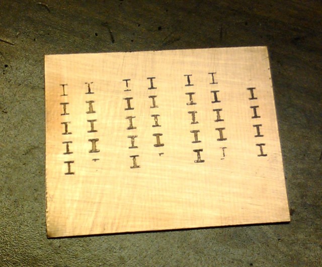
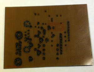
So instead, I used the laser to cut wholes in a small piece of acrylic to use as drill guide:

This gives you a pattern to follow using a Dremel and the holes wind up in the right places and nicely lined up. I drilled 2 holes in opposite corners of the board and used the leads from resistor to line up the template and board and hold them together while drilling.

This image shows the template attached to the board and about half the holes drilled. This worked very nicely! The only problems was small disks of acrylic getting stuck to the drill bit (you can see little craters on the left side of the board where these came from) I had to clean the drill bit twice to drill the whole thing. Either bigger holes or a different plastic might fix this.
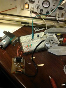 This is first of the 3 boards I put together and it works just fine. It is a level translator for the encoder you see in the holder. The encoder will be attached to the drive motor in my electric car and feed back motor position to the controller. The encoder is 5V and the controller wants a 15V signal. The test bed uses a 15V power supply and LEDs on the 4 quaderature outputs.
Encoder test video
 Today, I stopped in at the Makerspace with the plan to work on a small project for a Halloween party this Saturday.