My latest project is a 3D printer that will produce chocolate objects. Like many other chocolate printers, it will include a syringe to dispense the chocolate. Unlike those other printers, the syringe in my printer will have 3.5 liter capacity to enable printing large objects.
The syringe is made from PVC pipe using mostly standard fittings. One piece that wasn’t standard was the plunger that fits inside the syringe tube and pushes on the chocolate contained therein. I had to design and fabricate the plunger. PVC pipe isn’t perfectly smooth or perfectly round inside, so I needed something compliant enough to ride out the pipe’s bumps and constrictions while maintaining a seal. The seal needed to be tough, yet safe for use with food because it will be in contact with the chocolate inside the syringe. I found some food-grade silicone casting material and ordered it.
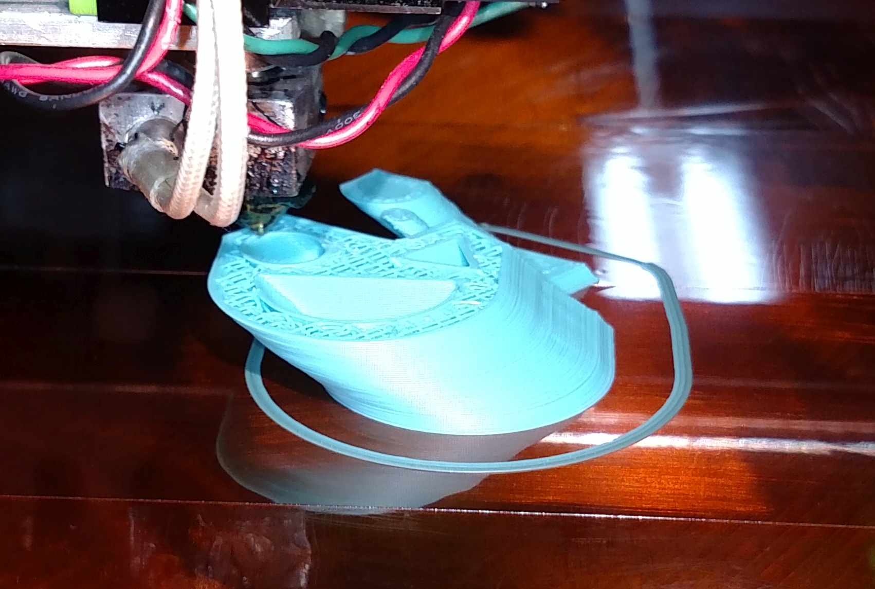
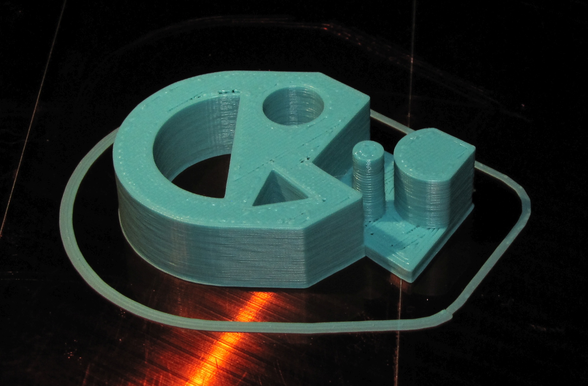
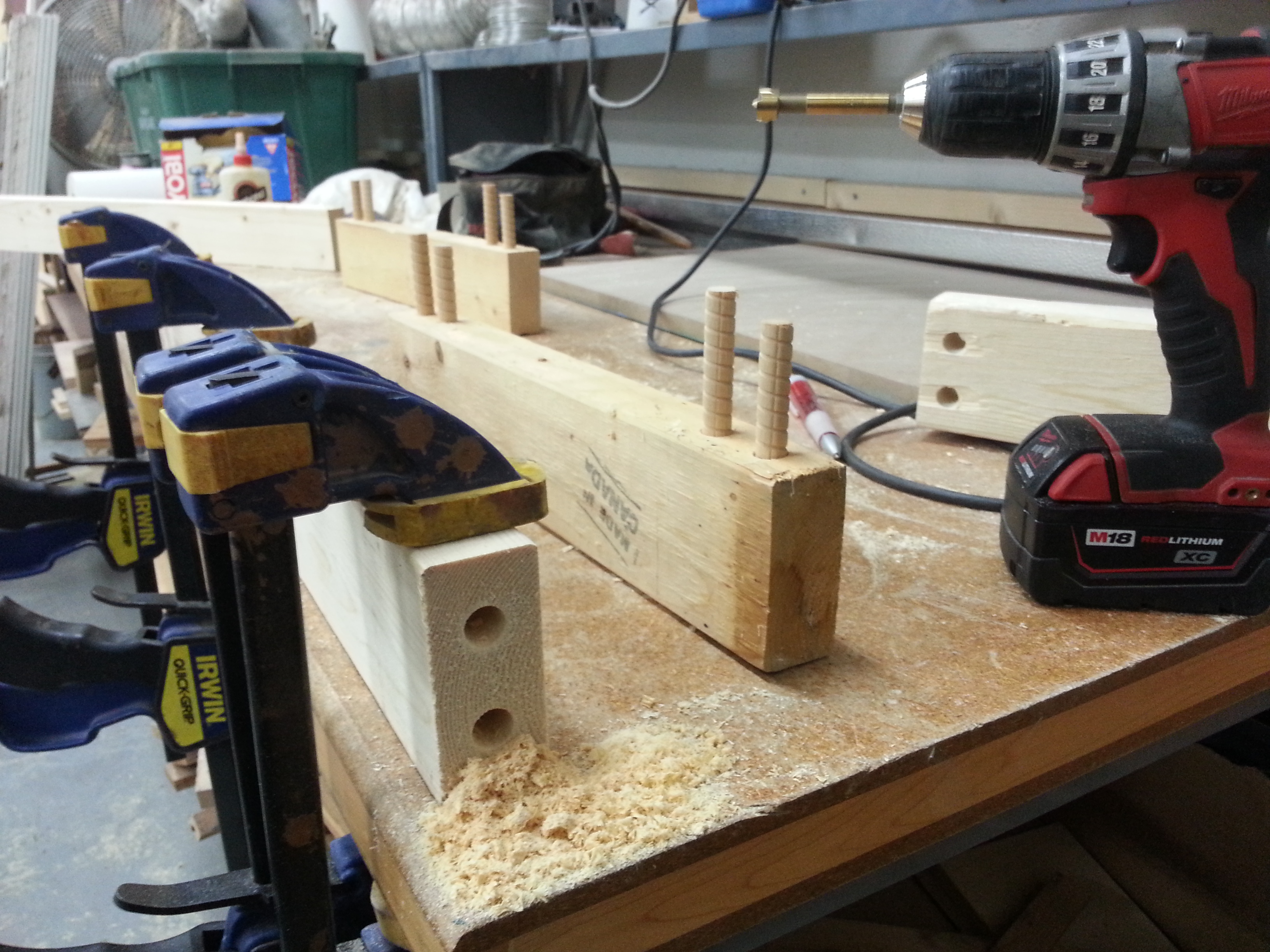
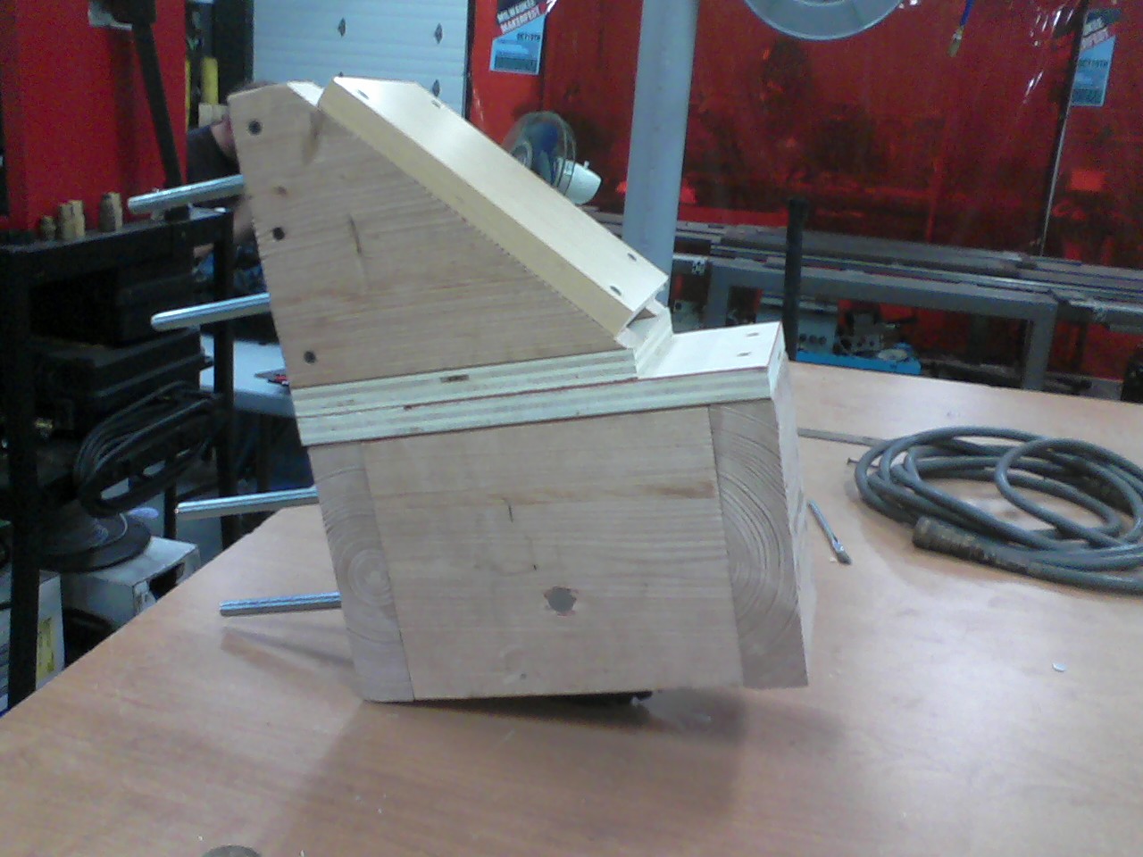
While waiting for the silicone to arrive, I designed a 3D printable core for the plunger and a mold and jig. The core fits on the end of a linear actuator that will provide the push. The jig centered the core a few mm above the bottom of the mold. The mold was tapered and the widest part -the bottom- was a few mm larger diameter than the pipe, and several mm larger diameter than the core. The silicone envelops the core and is locked in place by holes that connect top and bottom side of the core. The plunger squeeze-fits into the pipe to maintain the seal against the uneven inner surface of the pipe.
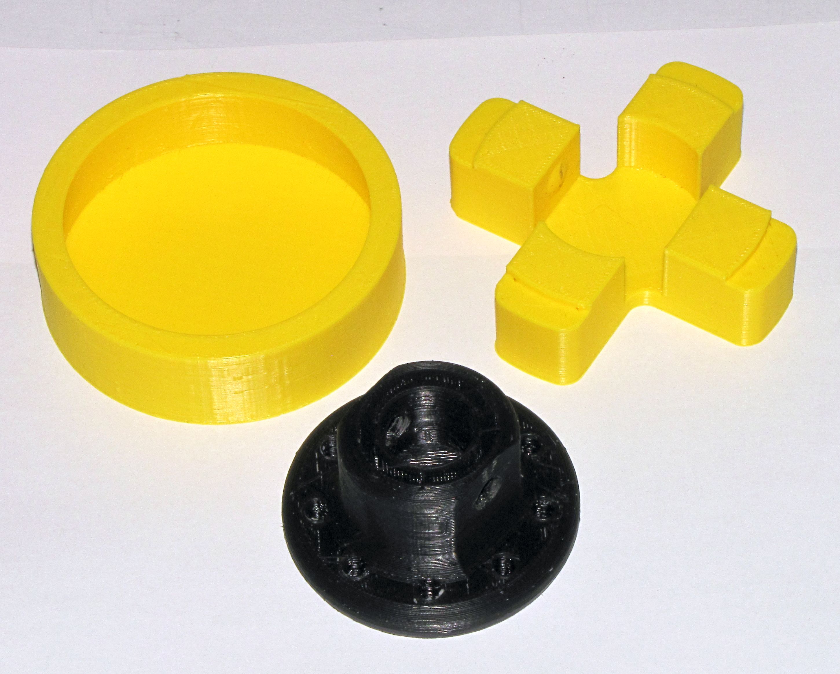
Mold, jig, and core for syringe plunger

Mold, jig, and core for syringe showing core inserted into jig.

Mold, jig, and core assembled for silicone over-molding.
I measured and mixed the silicone, coated the core with it and then set the core and jig in/on the mold and let it cure for 24 hours. Then I removed the jig and broke the now silicone covered core out of the mold. Result: a perfect, tight fit inside the syringe tube.
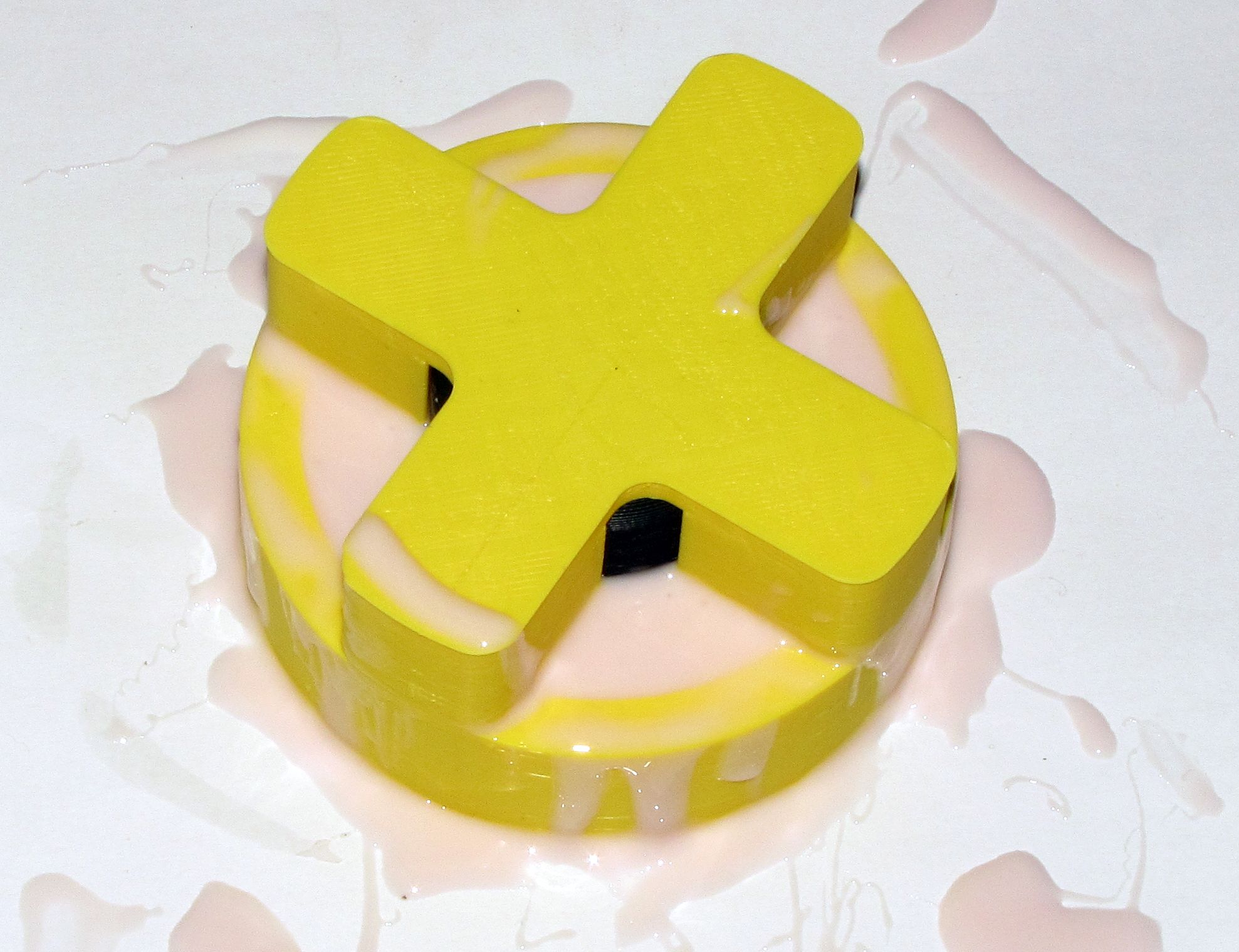
Core in mold with silicone.
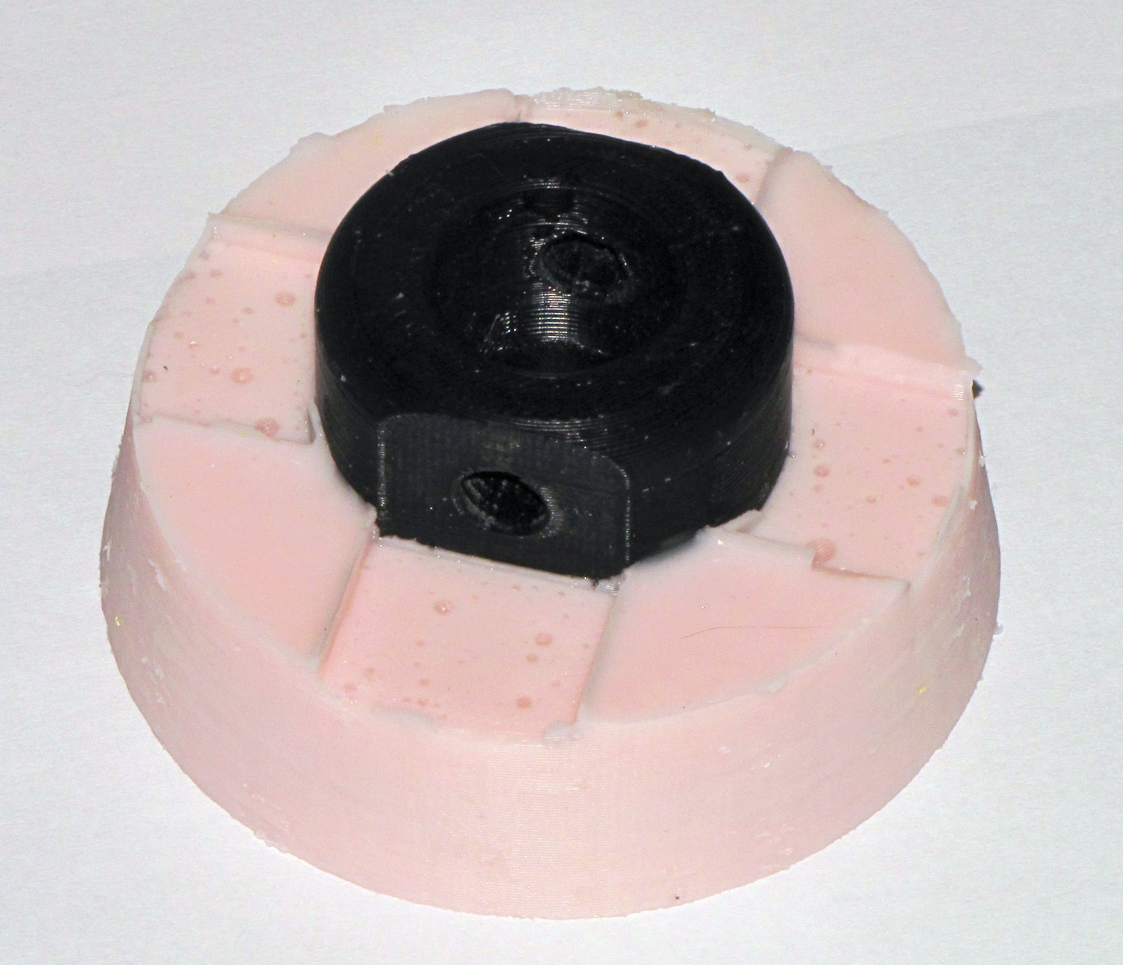
Finished plunger removed from the mold. The mold had to be broken off by design.

Plunger mounted on linear actuator.
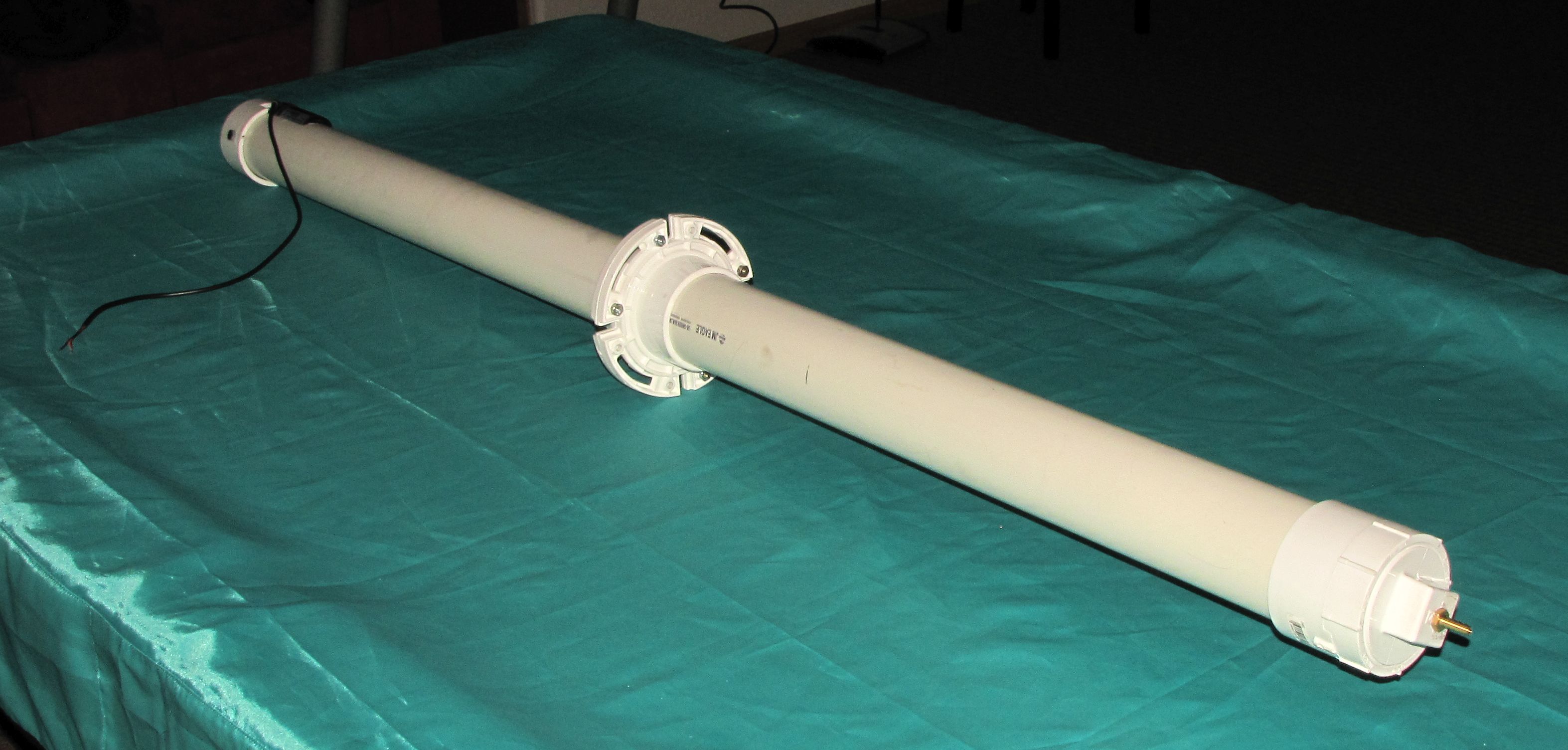
The assembled syringe.