Robbie is safely enclosed!

Finished room!

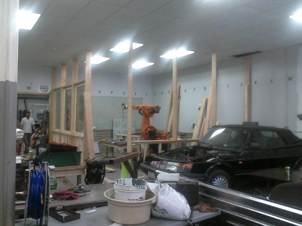
Whew.  This project was a D-O-O-O-ZY!  We needed to enclose our giant industrial arm so he can’t run away and join the robot circus…

Well…maybe not for THAT reason, but when we start cutting stuff with this robot, we need to keep spectators out of his reach and make sure that if a cutting bit does break, it doesn’t go flying out into the shop and maim someone.

This entire project was the work of several people and really shows why the Milwaukee Makerspace is a great place to build stuff/hang out with friends/play with power tools, etc…

———————————————————————————

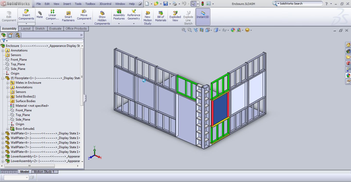
Step 1: Design it!  I used Solidworks and modeled each and every piece of wood that went into this project.

SW screen capture

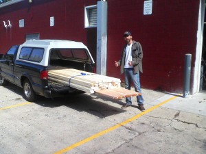
Step 2: get the wood!  We made multiple trips to Home Depot, which thankfully is only 5 minutes away and we had great weather during the whole building process.  I love having a truck!  Fortune also shined upon me, as we had a new member join up right before I started this project, Jake R., and his help in building the wall was immeasurable.

Get the wood!

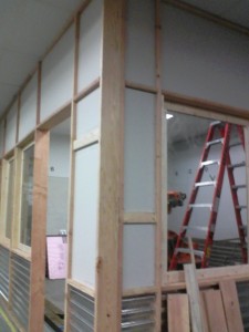
Step 3: Bolt the wood to the floor so we know where to put the wall, and then build some framing!

  4 - put in windows

Step 4: Put in the windows, drywall paneling and metal wainscoting.  We were very lucky to get seven pieces of slightly-smoked Lexan from one of our members, Jason H.  We also cut small holes in the ceiling tiles and ran 4 braces up to the metal ceiling trusses above.  This enclosure is ROCK-solid stable!  Thanks to Tony W. and Jim R. for helping with that!

When I went to Home Depot, I thought my truck could handle a 48″x 120″ sheet of drywall.  Not so much… one of their employees helped me split 10 sheets of drywall in half, in the parking lot…so I would later find out that I did not have drywall tall enough for the wall corner.  Hence the need for more “framing” so I could use smaller pieces.

10 - outer framing

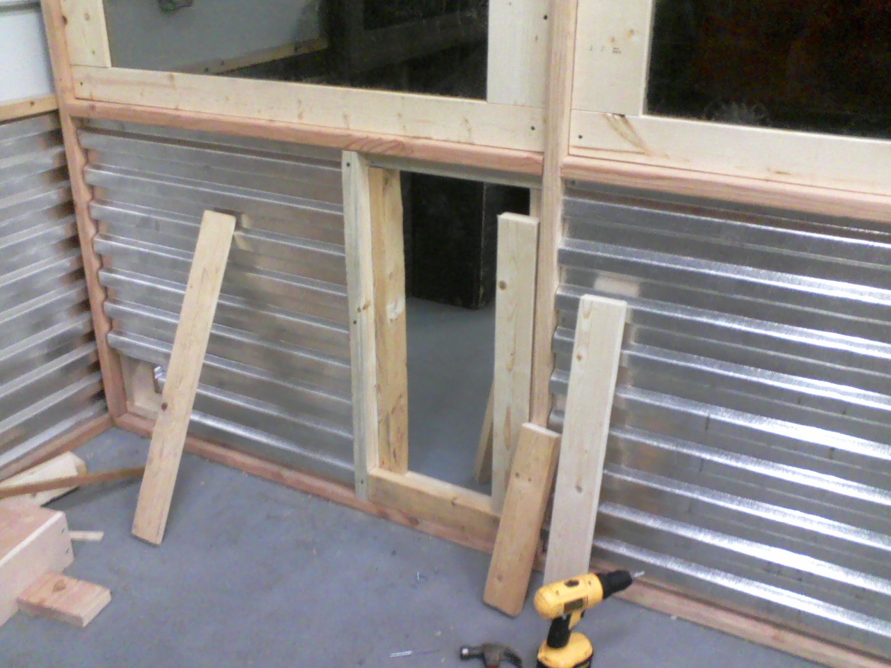
The large cabinet that powers the robot arm is right next to the enclosure; I placed it outside to keep it away from foam & wood shavings.  However, we will need to have the programming pendant next to the machine every now and then….hence the need for 2 small pass-thru doors next to the cabinet.

6 - hole for mini-door

11 - outer door installed


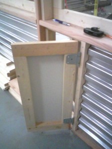
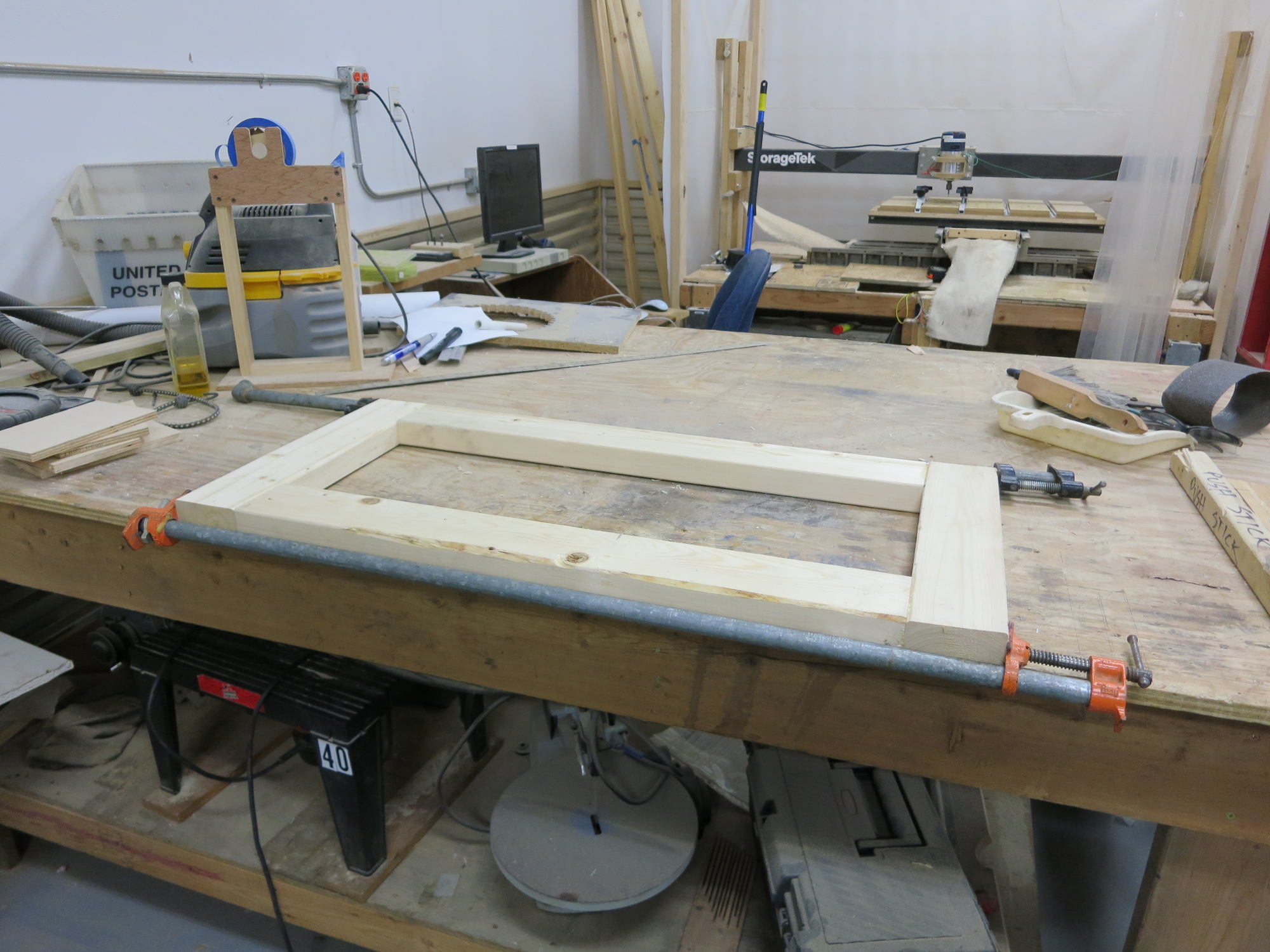
I used doweling to help hold the door frame components together…..probably not needed, but it ensures a STRONG door!

16 - drilling door frames  15 - door framing 1

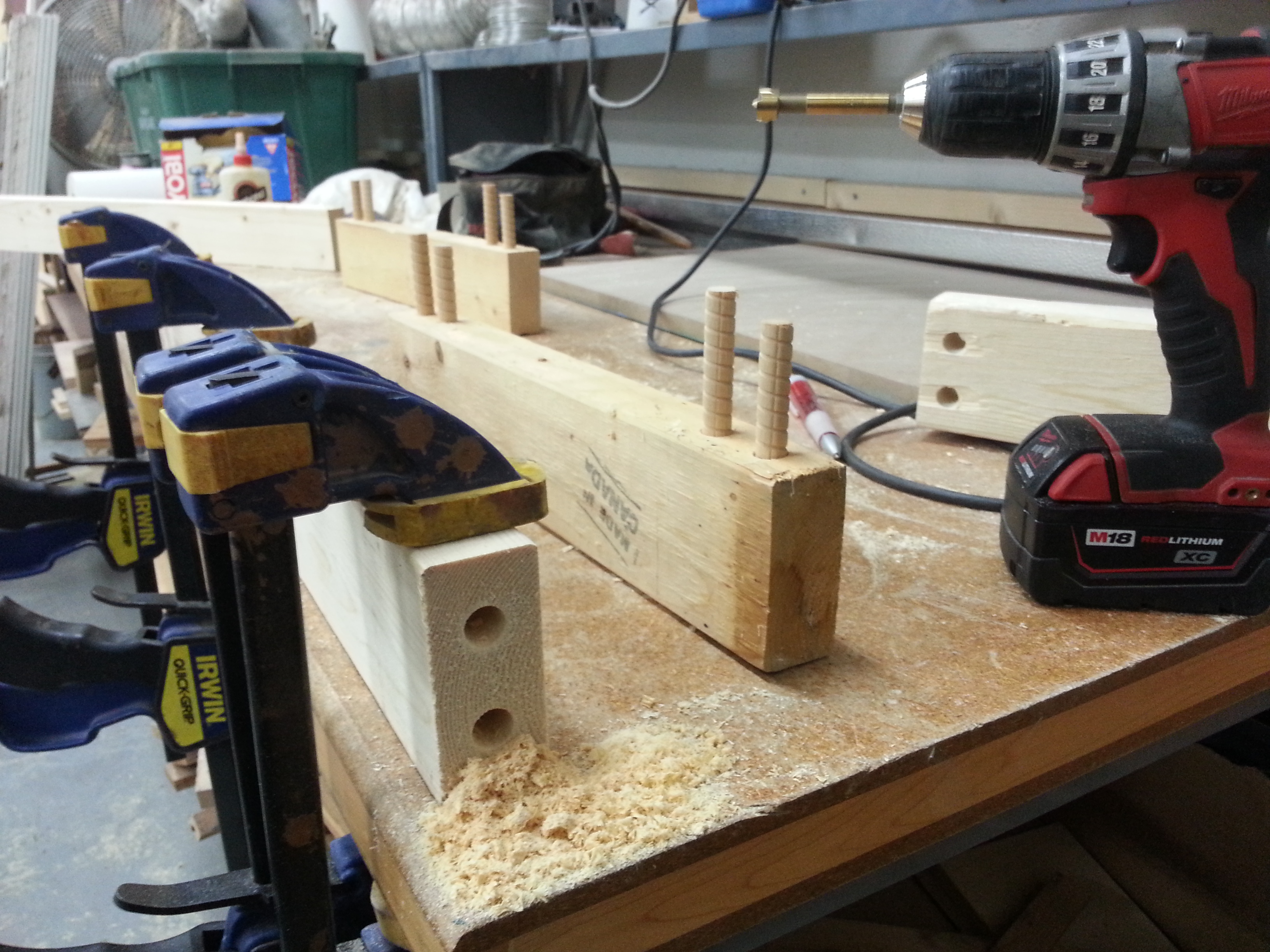
Again, hooooray for the Makerspace and all its tools! We have several LONG pipe clamps that came in VERY handy for gluing the door frame pieces together.

17 - frame glued up - 1

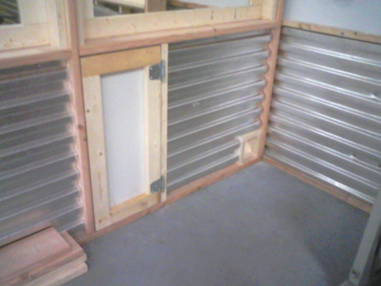
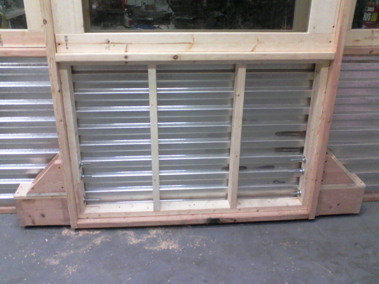
Here’s the outside of the enclosure.  The big metal control cabinet will go right here, hence the framed “mouse hole” in the lower right corner so we can pass the cables through from the cabinet to the robot arm.

13 - outer door and mouse hole

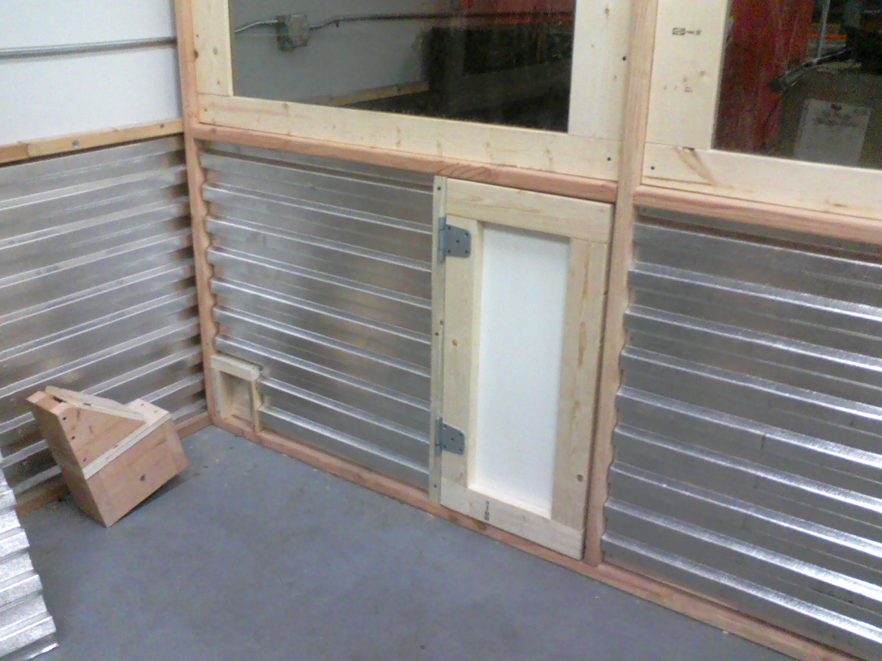
The same area viewed from inside the enclosure.

14 - inner door and mouse hole

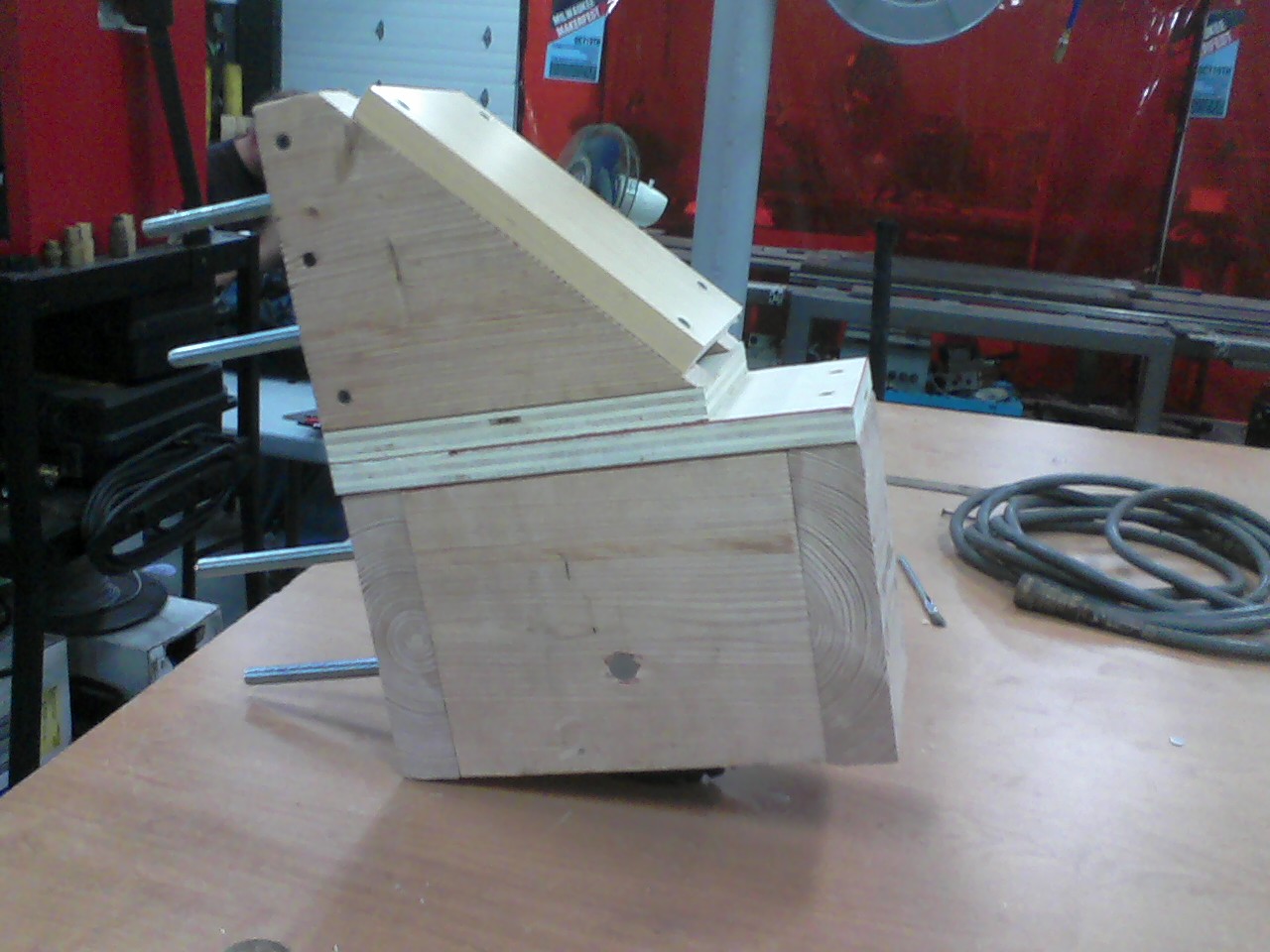
Here’s the ginormous sliding door.  It’s mounted on a barn-door track-rail and supported on the bottom by two custom-made wheel brackets.

23 - finished door on track

Here’s how I made the wheel brackets.  I got two lawnmower-style wheels and bearings from Tom G., then Tom K. enlarged the center holes on the wheels on his Bridgeport mill so I could use bearings for smoother action.

18 - wheels in slot - 1

I figured on four carriage bolts for a super-strong connection to the door frame.

19 - wheel assembly done

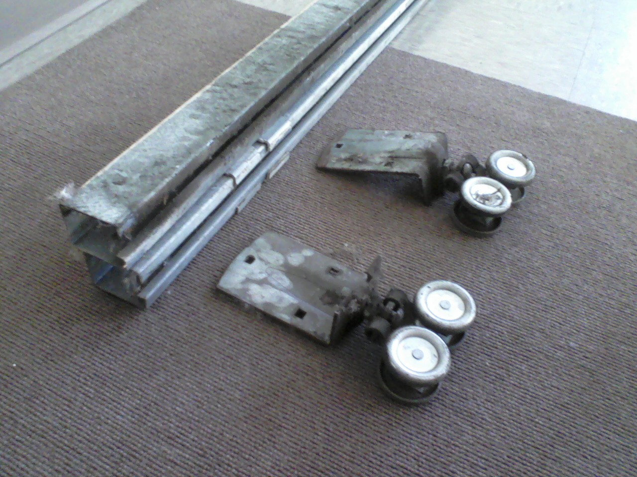
This is the track and wheel bogies that hold the sliding door to the wall.

22 - wheels and track

Bolting the brackets onto the door was “fun”…I forgot that the very bottom of the door framing is two horizontal pieces, so the very bottom bolt had to go.  ‘DOH!

21 - inside door frame 1

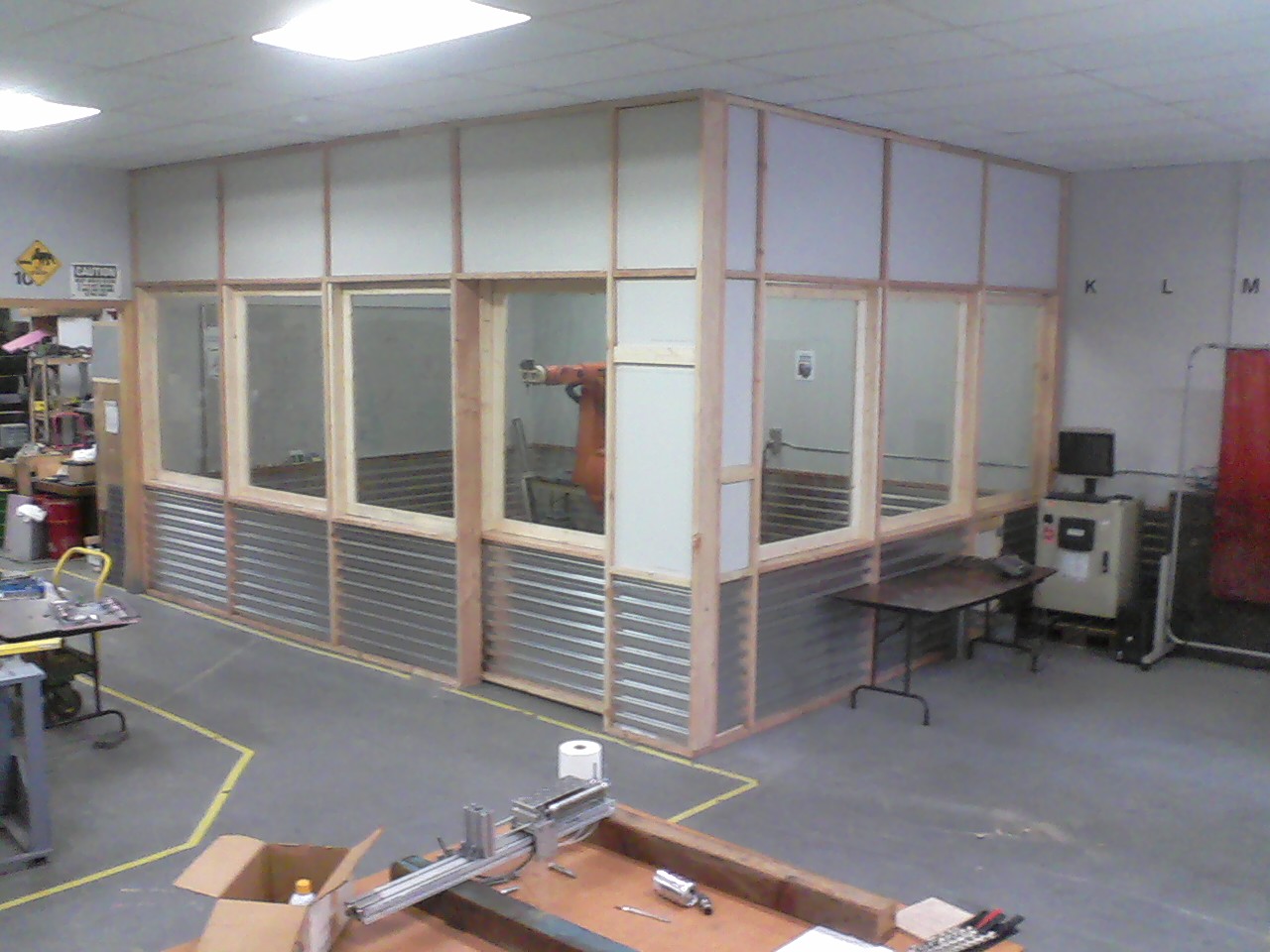
Here’s the final, assembled view.  You can see the robot’s control cabinet in the lower right corner.

Now that the fabrication is complete, we’re working on decorative ideas for all that blank-looking drywall.

24 - finished room!

Whenever I look at this finished project it feels like to took several months to get it up, even though construction only lasted about 2-1/2 weeks.

Thanks to Jake R., Tom G., Tom K., Tony W., Jim R., and Bill W. for their assistance with this project!

Robbie is nearly weaponized….


router clamp in foam 2
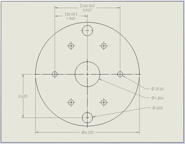
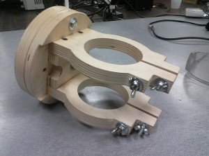
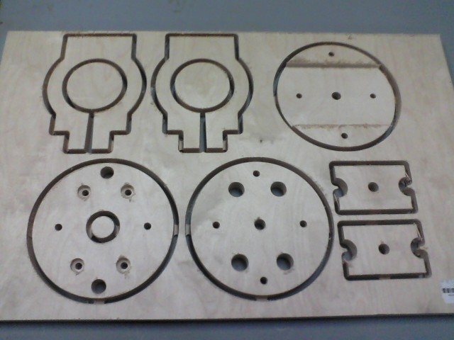
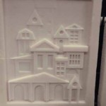
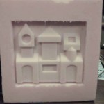
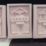
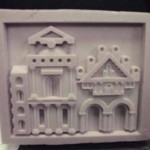
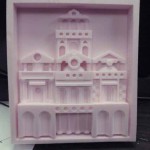
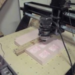
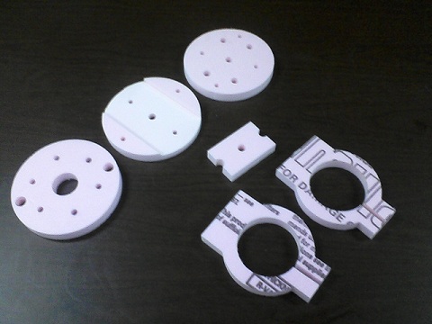
I am nearly done with a custom bracket for my Hitachi router that I will mount onto the end of our Kuka industrial robot arm.  I cut everything out in foam first to check  out the whole scheme and save wear and tear on the cutting bit.

flange for RobbieThe software chain I used to accomplish this was lengthy.  I designed all of these pieces in 3D in Solidworks, created a Solidworks 2D drawing, saved that as an AutoCAD drawing, brought that drawing into Vectric’s Aspire, then created machine code that the Makerspace CNC router used to cut the pieces from a sheet of foam.

finished clamp

Finally, once I was satisfied that everything would cut correctly, I switched to 3/4″ thick Baltic Birch plywood.  This is a “nicer” grade of plywood than the stuff that is used in day-to-day building construction work.  This wood is stronger by virtue of a greater number of plies, and it also looks nicer.  I happened to have a sheet left-over from a previous project, so it was all good!

plywood sheet

I am the Cult of “Foamy”

Hello all:

I have been a member here at the Milwaukee Makerspace for about 15 months now.  One of my favorite things to do here is machine architectural reliefs from foam.  I studied architectural history extensively at UWM, so I have a lot of influences to draw from.

The first piece I did was 3/8″ deep, since that’s the bit we had at MMS.  I first tried a piece with all flat surfaces.  It turned out very well, so I tried another piece that has slanted roof surfaces; again, success, so then I did some searching and found a 1/2″ deep milling bit.  I did several pieces “on a theme”, taking the first one and making slight modifications. All of these designs are my own creations, I just daydream and think them up.

I have found that I can get 1/64″ details on these pieces.  I have recently started using 1″ deep bits, and the results are fantastic!  The best part is that the foam is really cheep-cheep-cheep, $25 for a big sheet at Home Depot!

My process is:

1) design in Solidworks (CAD)

2) Export to .STL file format

3) Import into Cut3D, where I generate G-Code

4) Load into Mach 3, the software that controls the CNC router.

5) Let the foam fly!

I started out on the MMS router, which uses leadscrews; my newer Zenbot machine uses belts, and is blazing fast.  I can now machine 8 times faster!  The largest piece shown here went from about 19 hours down to 2.5 hours.

My next challenge is to get small lines onto my pieces that will represent bricks/mortar, etc.  I’ll have to generate different code for that; the milling code runs in 3d, but the “bricklines” will need to be in 2d, so I’m looking forward to that challenge.  I’ll be using Vectric’s “Aspire” software for that.  More to come!

-MattN


Magic Mirror Theater Prop

My sister is a Theater Manager at the Patel Conservatory in Tampa, FL.  About two weeks ago she texted me and asked if I could make her a prop she needed for an upcoming production.  “How keen would you be on making me a mirror for “Beauty and The Beast,” she said.  “They want a mirror that lights up and sparkles like the one from the movie.” Even with limited experience just tinkering around, I knew I could do something fairly easily, so I agreed and got to work.

I combined two different circuits (a 555 timer to flash and a RC circuit to fade) and built a wooden frame with acrylic plates for the front and back.  The wood and plastic were CNC-milled, then sanded and painted before the electronics were installed and glued into place.

The result was a fairly decent-looking, shiny, light-up hand mirror with a small thumb button on the right side that flashes 16 bright green LEDs when pressed.  It all runs off a single 9-volt battery and the back can be unscrewed to replace it should it ever die.

Total build time from start to finish was probably close to 15 hours over the course of one week.  The play was Thursday, July 19th and from what I’ve heard, it was a great success.  I’ll add pictures from the performance if I get some.

Casting Furnace Update

Despite summer vacation and other obligations, work continues to progress on the Casting Furnace.  In the past few weeks Bret has pinched the end of a metal brake line tube used to feed the furnace diesel fuel and installed a needle valve to better control the fuel flow rate.

Brant has been milling and machining parts for a mechanism that will both lift the lid and turn it out of the way when someone steps on a foot pedal.  The next steps will be to finish the foot pedal, weld it to the rig, and secure the lid to the top of of the lifting post.  Bret also plans to improve the casting tongs so they are more easy to use.

For more information, see the project wiki page: http://wiki.milwaukeemakerspace.org/projects/casting_furnace