EEVBlog’s Simple Soft Power

Dave Jones over at EEVBlog posted his design for a simple soft power circuit. This is something I looked at a couple of years ago in my own un-expert way. I really like Dave’s design. It’s just so simple and draws basically nothing when off.  It’s something I definitely want to file away in my library of circuits as I can see it coming in handy quite often.

If you are not familiar with EEVBlog you should check it out. Dave’s series of videos are fun to watch and you often learn something.

Li-Ion Protection / Softpower

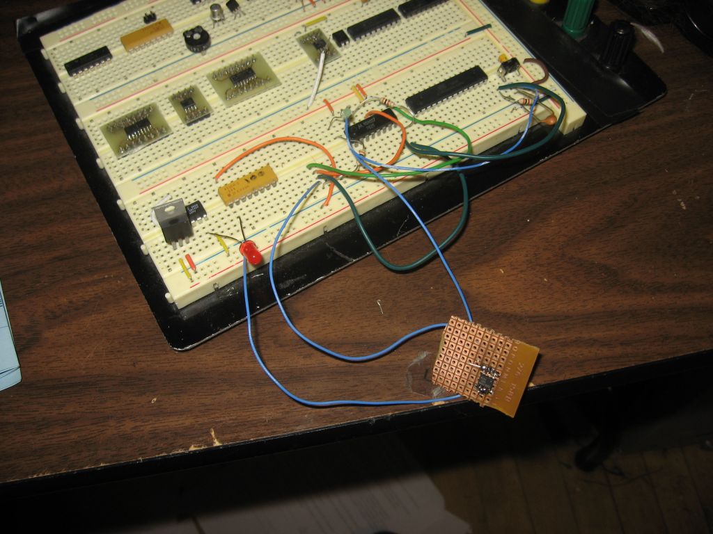
I got my softpower circuit to work finally. After numerous attempts and configurations using only a single N and single P channel I wound using two N-Channel FETs and one P-Channel. That’s more than I wanted, but I have the FETs already in only two chips, so, the heck with it. It works!

I have a working prototype of the schematic above. I don’t have all the caps or the voltage divider in place, but I don’t expect those to be serious problems.

I had a bit of a snafu with the MCU code during testing. I was using a logical AND operation in a conditional expression, instead of bitwise AND, while trying to read the PINB input register. It took me an hour and many experiments to figure out what I had done. The worst part was I knew I must have done something simple wrong but still could not see the obvious error for an hour! Grrr.

Ah, well. Now I have my circuit. It draws no power when its off, can switch off the power if the voltage gets too low and is push for ON, push again for OFF. 11.1V and 18A! I’m excited to get a full fledged PCB designed, etched, populated and smoke tested!

Li-Ion Protection Circuit mutating

Well…. the protection circuit did not work when I breadboarded it. I should have known. The output pin is only high impedance when the MCU is powered on. Powered off it lifts to a high voltage even when pulled down by a 3K resistor. This results in the transistor turning right back on again.

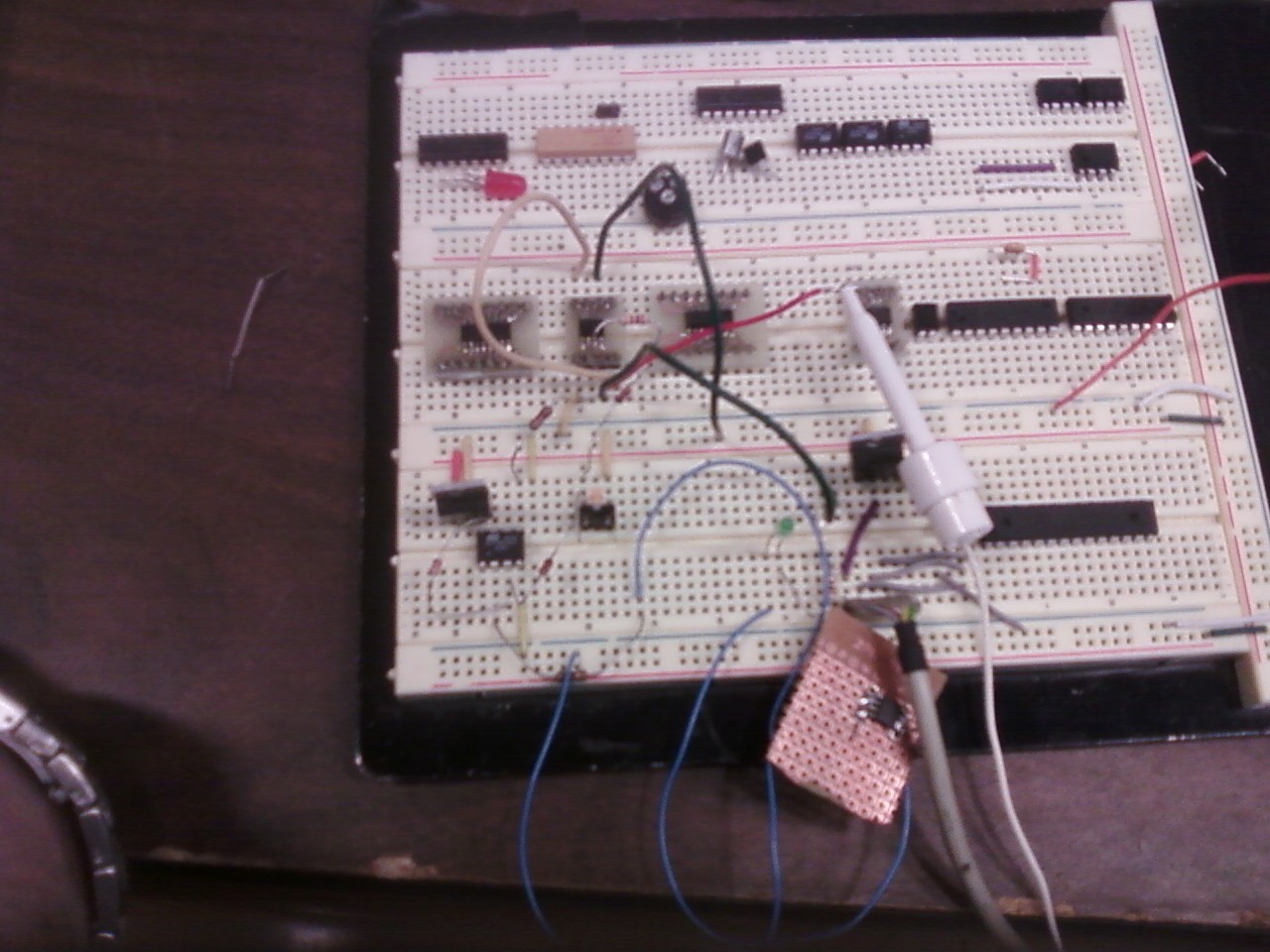
So, at TomG’s suggestion I am adding a CMOS J-K Flip-Flop to the mix. I don’t have the final design down just yet but I did breadboard up an early prototype. In the circuit pictured above, J and K are held high and Q goes to the gate of the power MOSFET and a 3K bleed off resistor. The button goes to the clock-in to toggle the state of Q.

The Flip-Flop power itself is not switched. Its hot all the time. The lowest setting on my multimeter is 200 uA. I was not able the detect any current draw at that level. Earlier I tried to used a bi-polar PNP transistor to fix my woes but I was only able to get down to minimum current of 200uA and a 0.67 voltage on the MOSFET gate. So, I think the J-K will be a winner

As of now circuit will properly switch the 5V regulator and MCU from the button with a only a small amount of button stickiness due to my weak debounce circuit, a 10nF cap in parallel with a 3K resistor to ground. The next step is to integrate the MCU into the power control. I may be able to take over clock control and just have the button force power to the MCU long enough to have the MCU pop the clock until it sees a High on Q.

I’ll give that concept a go next time.

My Li-Ion protection circuit

I’ve been working on a protection circuit for medium large Li-Ion battery packs. The target application is a remote controlled car chassis, converted into a robot, and a Bioloid 20 servos humanoid robot.

The features I am looking for are:

  1. Soft power switching
  2. Over Discharge protection
  3. Fuse

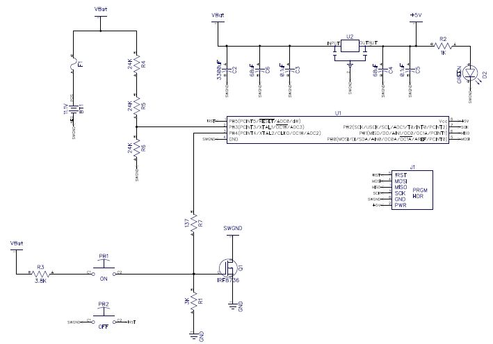
To get that I’m going to use an ATtiny45, because I have a bunch of them, and the IRF8736 TTL switching mosfet that is good for 18 Amps. The mosfet connects or disconnects the ground from the load circuit to avoid any issues with the required gate to drain voltage.

Switch PB1 is how the circuit gets turned on. That switch allows current to flow through the voltage divider formed by R1 and R3. The divider winds up putting just a little over 5V on the mosfet gate when the battery is fully charged and some where a little under 4V when the battery is getting empty. Even 4V should be enough to get the voltage regulator to fire up the ATtiny which then powers up pin PB4 to hold the mosfet open with 5V.

Switch PB2, resets the ATtiny which in turn puts PB4 into high impedance mode allowing the mosfet gate to drain to ground via R1. Thus the device is turned off.

I’m only in the design phase now. The circuit seems good, but I still need to breadboard it to make sure it works as I think it will. But that’s another post.