


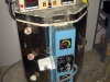
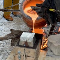
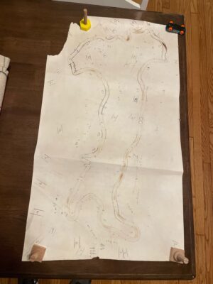
Iron Casting: January Iron Pour
This gallery contains 34 photos.
This last Saturday, January 13th we fired up the Cupola Furnace, R2V2. We had a small attendance due to the weather and were just a little bit delayed due to the roads. We had just enough molds on the pour floor. No one got injured and the metal was hot. This time I laid the […]
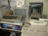
Neon Italy
Another neon project from Peter Merrick.
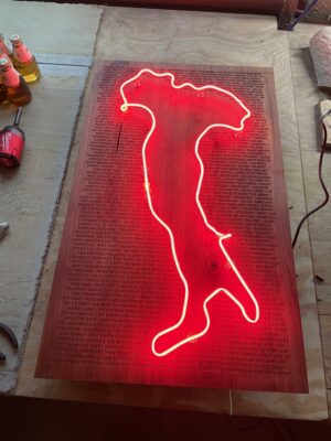
Background on this piece. This is the Italy “boot” in neon mounted to Walnut with engraved text. It is to commemorate a family vacation I took to Italy this year with the engraved text coming from sayings that we picked up from the trip.
Some detail on the process. The bending of the glass tube took roughly 15 hours over the course of a week. The Walnut was purchased rough, planed and jointed at the makerspace to get the boards square, and glued up into a panel. The panel was then cut down to size and run through the drum sander to even out any imperfections from the glue up. The engraved text was designed using inkscape and imported into CorelDraw for printing on “Katy Perry”, the 30W laser cutter. This panel was at the max cutting area for Katy Perry at 32″ x 18″. The cut took nearly 6 hours to complete. A box was constructed for the back of the panel to be used for concealing the electronics as well as a mounting point for the French cleat.
Total time to complete this piece was roughly 50 hours over the span of 2 weeks. Total material cost including glass, transformer, wood, stain, filling the tube with neon gas, and time on the laser cutter was roughly $200.
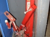
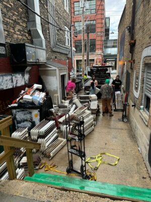
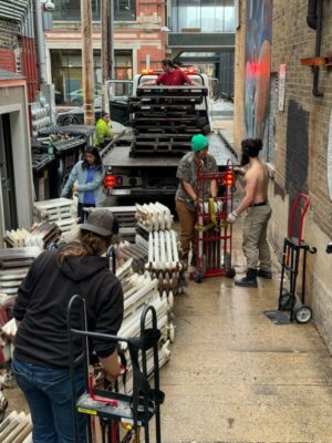
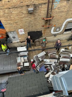
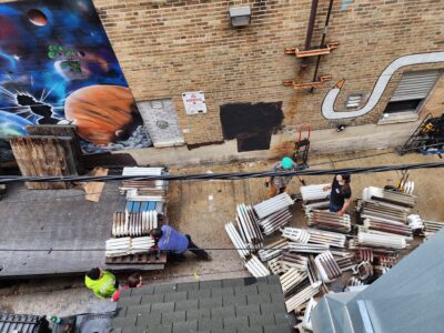
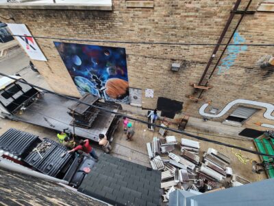
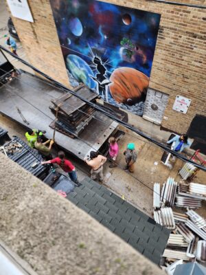
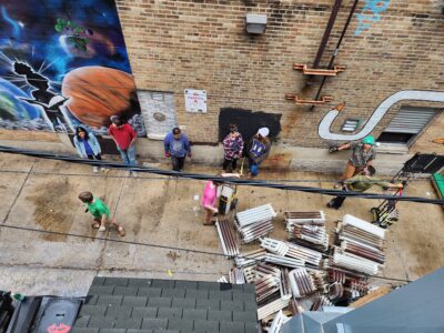
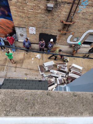
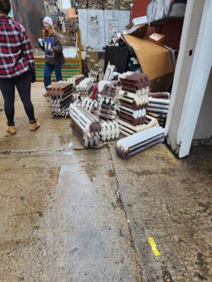
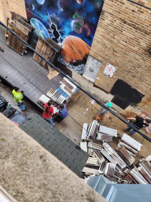
Iron Casting: Radiators
Thank you everyone who helped out today hauling two loads of radiators to the space for iron casting. A total of 7 tons of iron. Feel free to come by Wednesdays at 5pm at Norwich to learn more about getting involved.
The next Artist Tile & Doodle Bowl Workshop is Devember 17th at 12:30pm, contact Dave Arnold for more information on upcoming

Happy Makes-Giving!
Introduction:
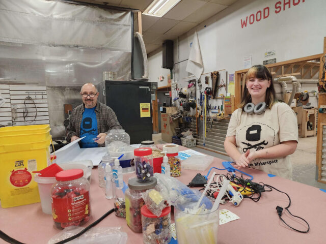
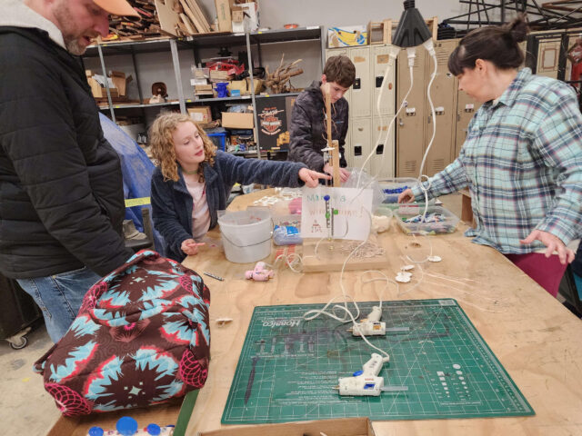
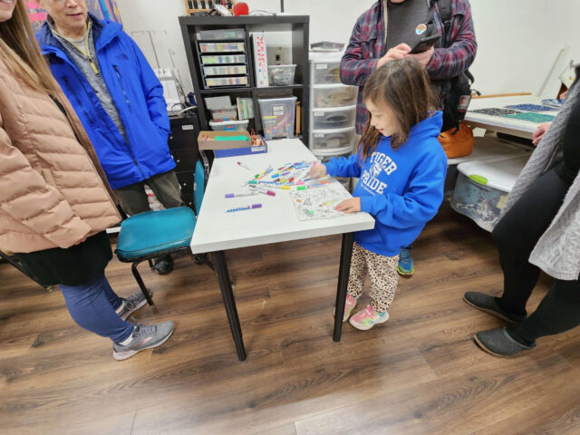
As the aroma of Thanksgiving dinner still lingers in the air and the first ornaments find their place on the tree, it’s that magical time of year again when we come together to spread holiday cheer through the community. While some brave the chaos of Black Friday sales to secure the hottest toys of the season, here at Milwaukee Makerspace, we have a different tradition. It’s our annual Makes-Giving event, a heartwarming celebration of crafting, community, and the joy of giving.
Making Memories on Black Friday:
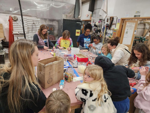
While many were out battling the crowds and long lines, our makers and volunteers gathered on Black Friday for a truly special occasion. Makes-Giving is an event that warms our hearts just as much as the hot cocoa warms our hands. It’s a day where we channel our creative energy into crafting thoughtful and heartfelt gifts for loved ones.
The Spirit of Makes-Giving:
At Makes-Giving, the spirit of giving is at its brightest. Members of Milwaukee Makerspace volunteer their time, expertise, and creativity to help families in the community create Christmas gifts from the heart. It’s a tradition that embodies the true essence of the holiday season – generosity, togetherness, and the joy of making someone smile.
Crafting with a Purpose:
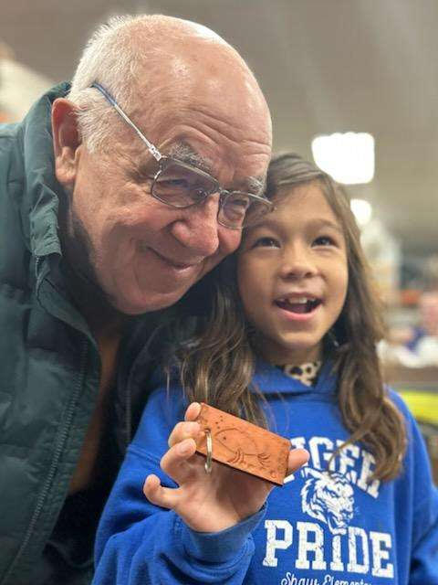
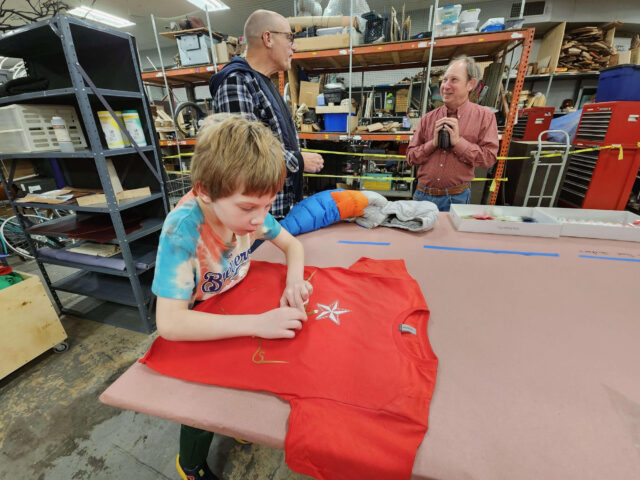
Our annual event isn’t just about making crafts; it’s about making memories. Families and individuals join us to craft one-of-a-kind presents that carry their love and personal touch. From handcrafted ornaments to custom-made keepsakes, the possibilities are as endless as the smiles they bring. Makes-Giving isn’t just a crafting event; it’s an opportunity to create cherished memories that will last a lifetime.
Mark Your Calendar for Next Year:
If you missed out on Makes-Giving this year, don’t worry; there’s always room for more holiday magic. Be sure to mark your calendar for next Black Friday and join us for a day filled with creativity, community, and the joy of giving. It’s a chance to slow down amidst the holiday hustle and bustle, savor the simple pleasure of crafting, and make a meaningful impact on the lives of those you love.
Conclusion:
As we hang up our crafting tools and put away the glitter for another year, the spirit of Makes-Giving lingers on in our hearts. It’s a reminder that the holiday season is about more than just presents; it’s about the love, connection, and joy we share with one another. So here’s to another successful Makes-Giving, and to many more in the years to come. May your holiday season be filled with warmth, creativity, and the joy of giving!