Last minute decisions work out once in a while. For example, I was going to be at the Makerspace booth at the Milwaukee Maker Faire for the weekend and wanted some examples of the sorts of things you can use a 3D printer to make, so I grabbed the usual collection of sample prints, and then I thought, “sure, why not?”, and loaded the Van de Graaff generator into the car. It sat on the floor in the booth for about 1/2 of Saturday and I was getting a little bored, so I moved it closer to the foot traffic and plugged it in. Wow! Kids and adults with stunted emotional development went nutz! They were zapping themselves and each other as if it were more fun than painful.
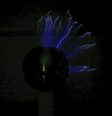
Sparks! The VDG produces about 400 kV.
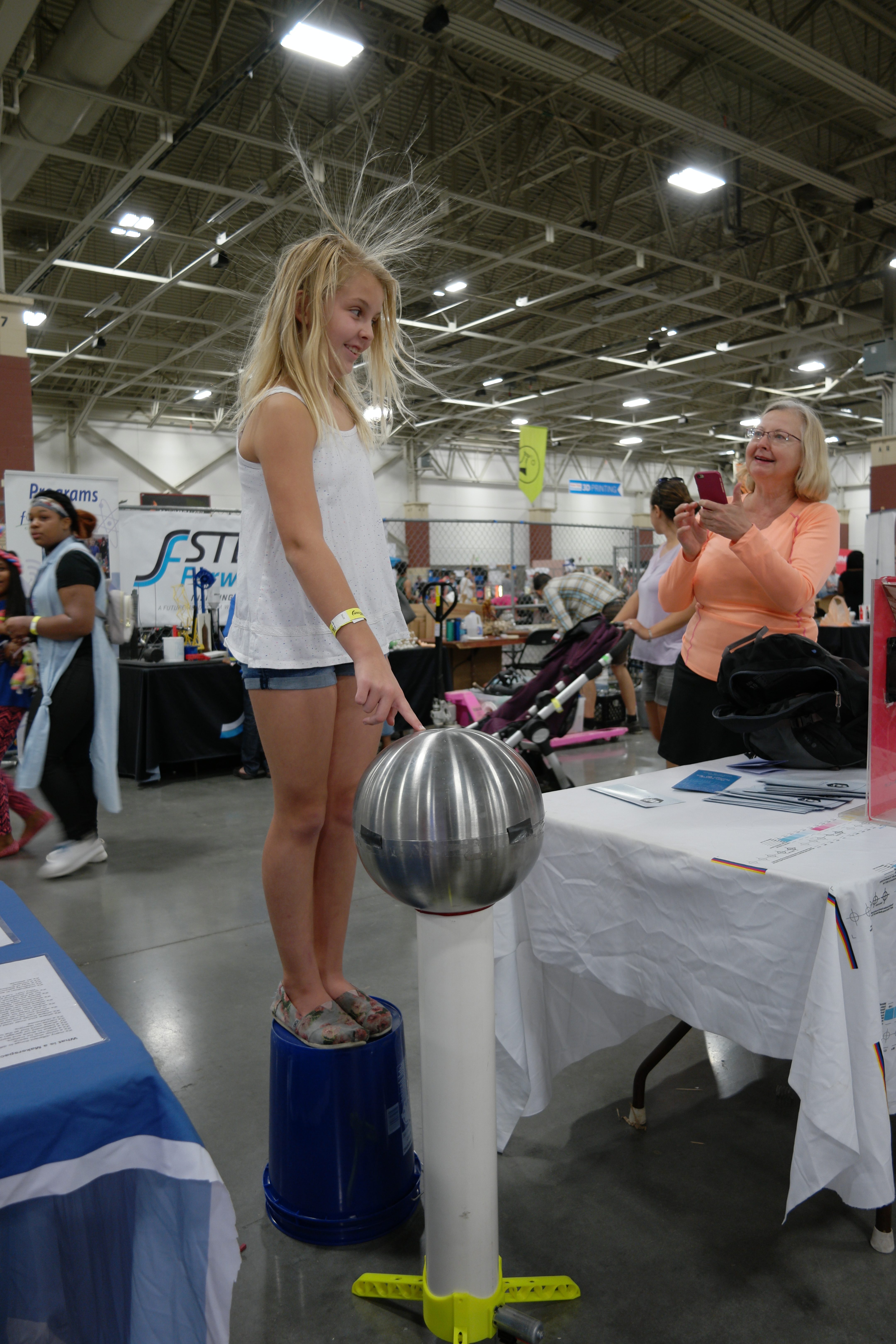
Then I found a plastic bucket and the fun really started. We had kids and many adults who were definitely much too heavy, standing on the bucket and making their hair stand up with moms, dads, boyfriends, girlfriends, husbands, wives, partners all taking pictures. I had to move one gentleman who was breathing oxygen from a tank away from the machine. Fortunately, no one fell off the bucket or caught on fire, and next year we’ll do it right and take a block of styrofoam for people to fall off of to stand on.
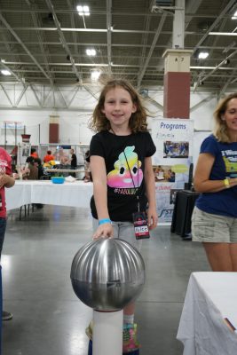
Kylee was ready to join the Makerspace just for this… and with that shirt, she’d fit right in!
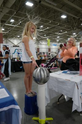
Blondes really do have more fun!

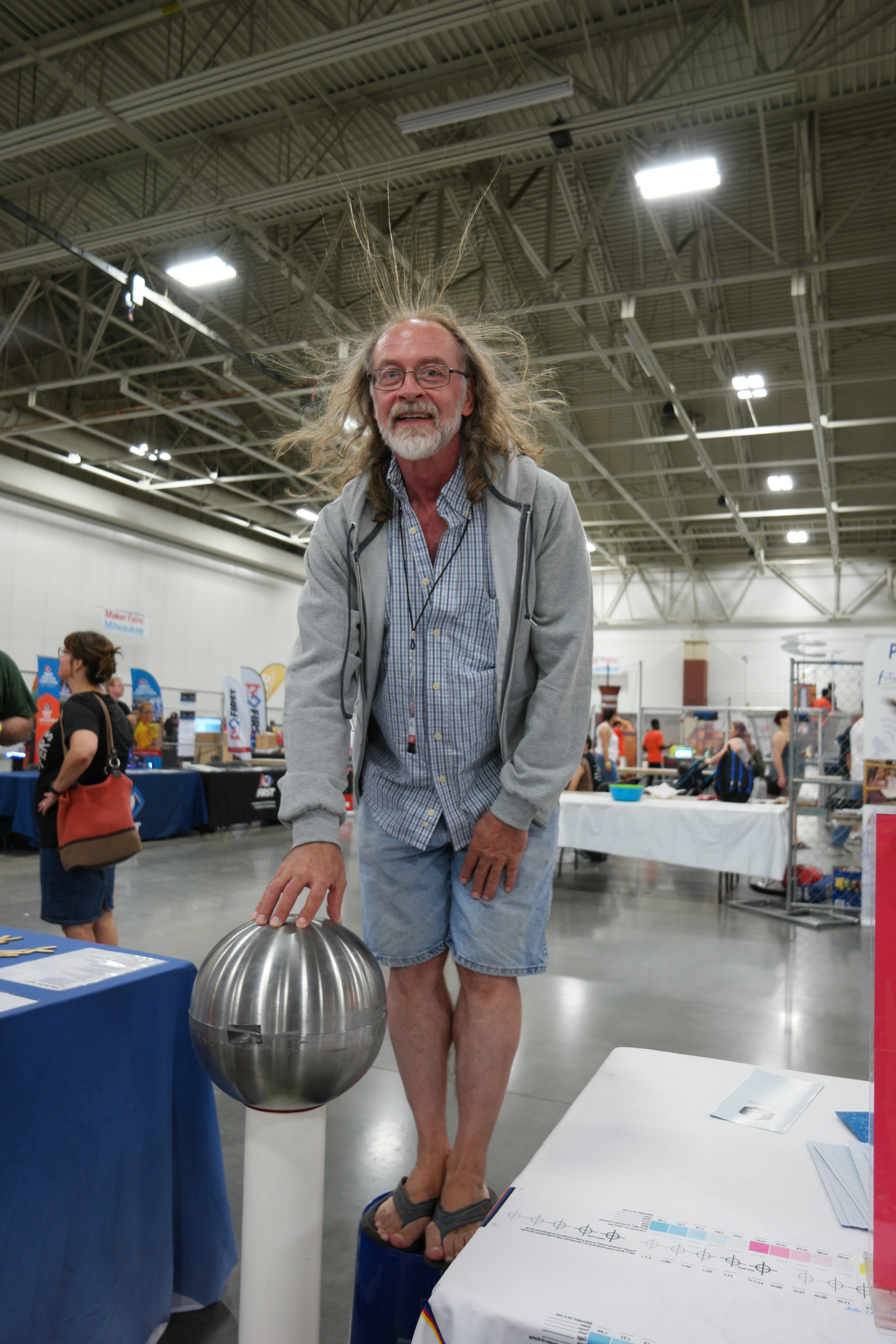
Even Gordon couldn’t resist!
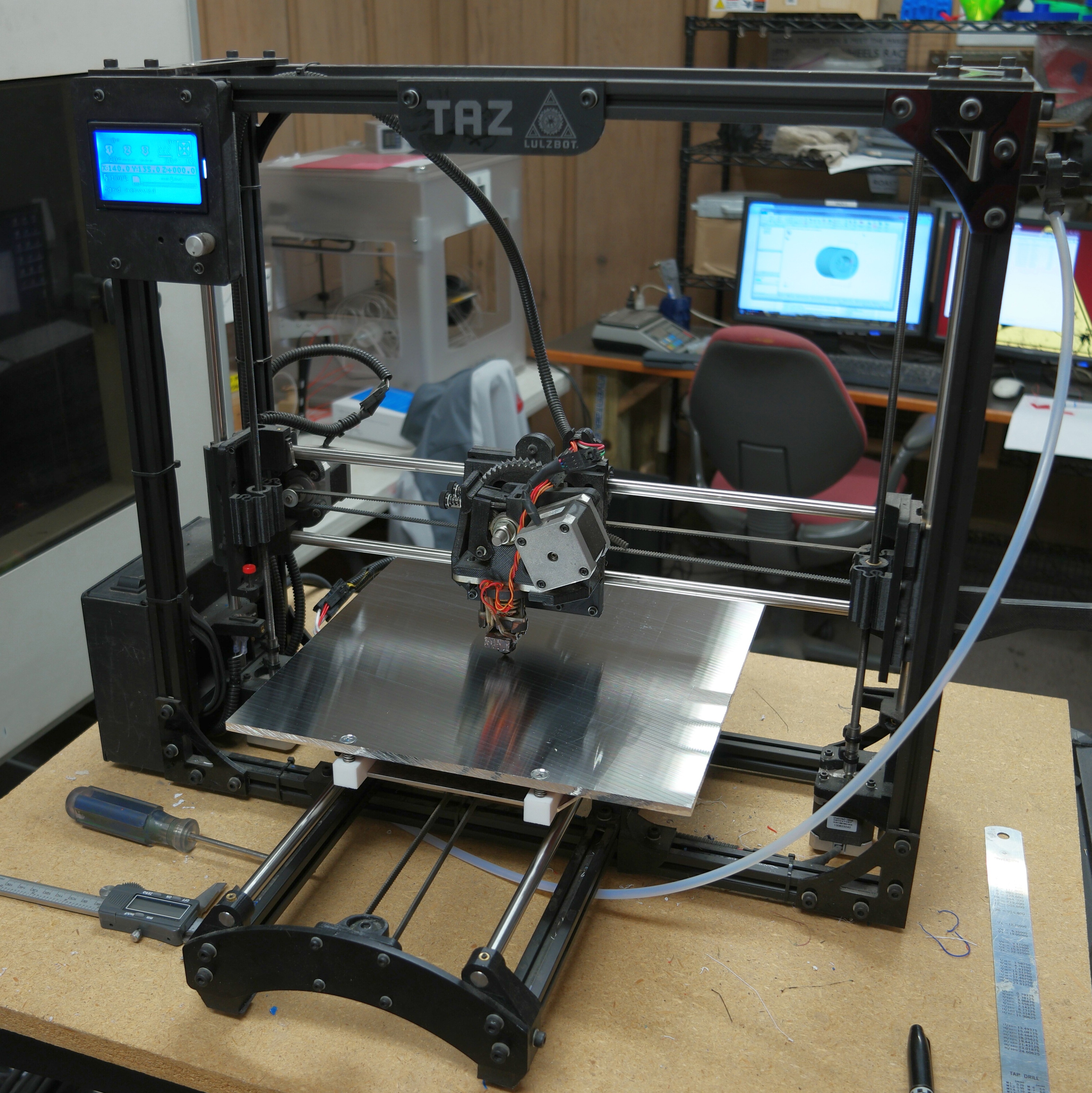
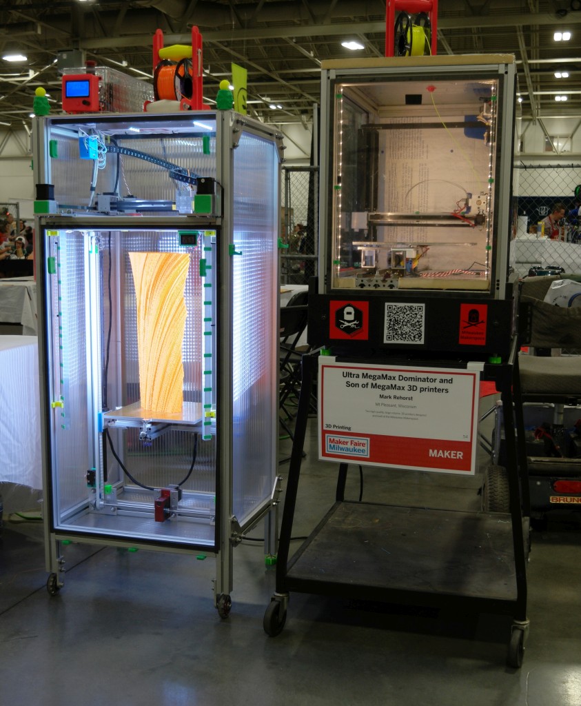
Last year Son of MegaMax (a 3D printer built at the Milwaukee Makerspace) went to the Faire. This year he had two companions to keep him company- an extra-beefy printer being built by Erich Zeimantz: MiniMax XY. MMXY isn’t complete yet, but promises to be a super high quality, high speed printer. He’ll be operational at next year’s Maker Faire. SoM also brought his big brother, Ultra MegaMax Dominator, named that because he is ultra, mega, maximum, and he dominates.
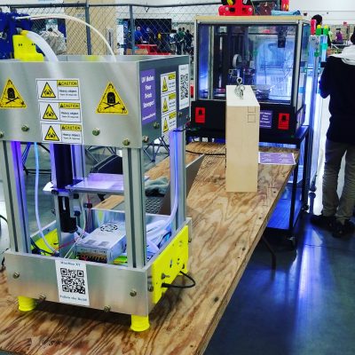
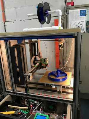
MiniMax XY at Milwaukee Maker Faire
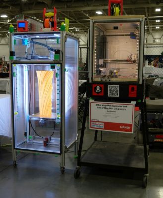
Ultra MegaMax Dominator and Son of MegaMax at the Milwaukee Maker Faire
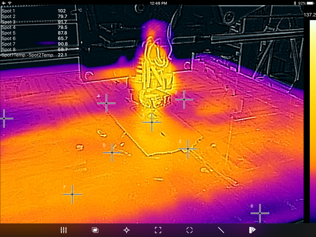
UMMD and SoM rotated between the booth and the dark room where the both printers’ UV lighting and fluorescent filament was a big hit.
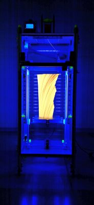
UMMD in the Dark Room at Milwaukee Maker Faire 2017
We had a few things besides 3D printers at the booth. Tony brought in some Bismuth crystals to give away, and surprisingly, they didn’t all disappear in the first hour. Tony thinks people left them because the Makerspace logo on the info board on which the crystals were sitting looked a lot like the skull and crossbones that usually indicates poison. The crystals do have an other-worldly toxic look about them. Oh well…
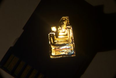
Bismuth Crystal
Marcin’s LED signs on the table at the booth and hanging above the entrance to the Dark Room were also very popular and hard to miss, though I managed not to take any pictures of either. The one above the Dark Room was so bright that if you saw it, you’ve probably still got its image burned into your retinas.
Everyone involved had a great time and we’ll be there again next year with even more cool stuff!


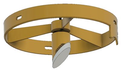
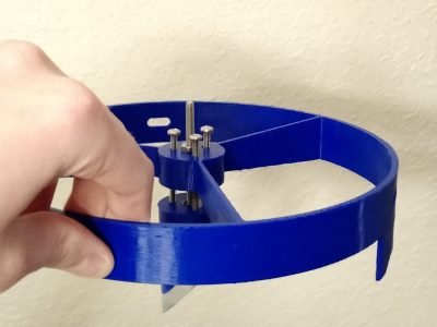
 The spider snugly fits in an 8″ diameter tube. There are 3 slots in the perimeter to allow rotational alignment along the axis of the tube. There are 3 additional screws in the central cylinder that tilt the diagonal mirror holder and provided height adjustment. The diagonal holder has multiple grooves to provide more surface area for the silicone to bond to. The surface the mirror mounts on is on a 45. The entire thing was printed in PLA on Mark’s SOM printer (huge thanks to Mark for helping out).