RN-42 Carrier Board

image

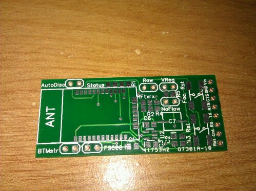
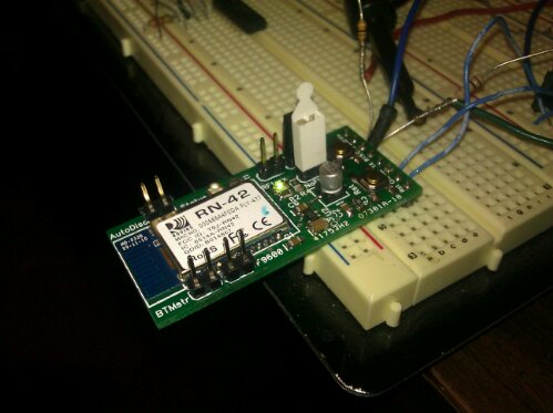
I got that RN-42 carrier board populated and working! Its ready for the GyroSkirt driver board, once I get that built.

There are a few errors on the board. TX and RX are swapped somewhere. Either on this board or on my USB to TTL-Serial board or in the RN-42 documentation. Also it seems the LEDs were meant to go to Vcc rather than ground. As a result my LED indication for connection status and RF traffic is inverted.

I can live with the errors as the actual data transmission works like a champ. To test the tranmission I hooked the carrier board up to a PC via a USB to TTL serial converter configured to operate at 3.3V.  The venerable Hyperterminal program was used to open the virtual com port on the PC. Then I downloaded Sena’s Bluetooth terminal program to my Android phone and used it to form a Bluetooth serial connection between my phone and the modem. The result: keys pressed on my phone’s keyboard appeared inside the Hyperterminal running on the PC and keys pressed on the PC keyboard appear inside the Sena Bluetooth terminal running on my phone. Bi-directional data flow at 115,200 baud.

Now that I have proven my wireless link works, I need to update the GyroSkirt/GryoBelt firmware to allow me to adjust the gain and the deadband over the Arduino’s serial port.  (In addition to actually making a driver board that has a spot for the modem.)

iTead Boards

image

I got my first batch of iTead Studio boards in!  iTead Studio is a  pcb printing shop that offers absurdly cheap prototype boards. The new boards look great. I’ll definitely use them again. It only took 2 1/2 weeks to get here. For the price its an awesome service.

The particular board shown is a carrier board for the RN-42 Bluetooth modem, which is only $15 from Sparkfun if you buy it in its surface mount form. For another $15 I now have 10 12! carrier boards that allow me to adapt the surface mount device to through hole technology as well as control infrequently utilized device specific features such as factory reset, BT Master mode, force 9600 baud and more. The more you know the cheaper electronics gets.

The carrier, populated with the modem, etc., is destined for the GyroSkirt. The idea is that I’ll be able to adjust the gain and deadband processing on the gyro sensor reading wirelessly from a program on my Android phone via the Bluetooth radio in my phone and one of these boards affixed to the GyroSkirt driver. The GyroSkirt will again be driven by an Arduino,  so I hope to leverage the Amarino library to speed my development time.

Carrie tests the GyroBelt

Tonight, at the Bayview Bash, Carrie tested out the GyroBelt to live Salsa music. As you may remember from previous posts, the GyroBelt is a prototype device for what will eventually become an eFashion skirt. The prototype and the skirt both try to avoid the Christmas tree effect by only illuminating the LEDs under certain conditions. Namely a high speed dance spin as detected by a MEMs gyroscope.

Gyro Belt Driver PCB

Pictured above is the driver board of the GyroBelt. In the lower right you can see the red SparkFun Gyro breakout board. Immediatly above that are the four transistors that lead out to the bus for the LEDs. (In addition to mono chromatic LEDs the driver board also supports RGB leds.) To the left of the Gyro you can see an ATmega168 running an Arduino sketch. Above that are a couple trim pots that I use to adjust variables within the sketch. Continue reading

Gyro graph of double spin.

Graph of Gyro output from Carrie doing a Double Spin in SalsaA quick graph of a double spin. This time it was to music instead of just counting.

I think for a first pass we’ll try a combo of intensity and color change.  I’ll add a Teensy to the belt and wire up half RGB leds and half Blue leds. The RGBs and blues will both be off in between 450 and 350 since the zero rotation value seems to be 400, ignoring the filter’s charge/discharge curves. Once the rate of spin exceed these values, on either side I will begin ramping up the intensity of the blue leds proportionately to rate of spin. The RGBs in contrast will have (relatively) constant intensity but will change color proportionately to the rate of spin and the spin direction. The color at 450 and 350 will be yellow-green. However, as the rate of spin increases toward zero, the color will shift to the red. As the rate of spin increases above 450 the color will shift toward violet.

I’ll put switches on the belt to allow me to select between RGBs and the Blues so that we can see what looks best.

GyroBelt Reading

Gyro sensor graph of spin plus head roll

Relative Rate of Spin vs. Time

Today my wife and I tested out the Gyro Belt. We recorded once specific dance move, what we call the Alex head roll. (We don’t know its real name, the dance teacher who taught us was named Alex) The flat part of the graph, you’ll notice, starts pretty flat and then begins to pick up some noise. After that the large pulses come in. Although were not able to take video, the move entailed a moment of standing still while I counted beats in preparation, two complete Salsa basics followed at last by the multi-turn head roll move.

As you can see the move registered quite nicely on the graph. But this is a simple move in isolation. Later we’ll test the reading inside of an entire dance routine. I would expect the signal to noise ratio to drop substantially, but we’ll see.

Once thing I do notice, that is curious, is that the resting level at the end of the chart is different than the resting level at the beginning of the chart.  That may give some trouble later depending on how much that zero rate level drifts. We’ll see.