Well…. the protection circuit did not work when I breadboarded it. I should have known. The output pin is only high impedance when the MCU is powered on. Powered off it lifts to a high voltage even when pulled down by a 3K resistor. This results in the transistor turning right back on again.
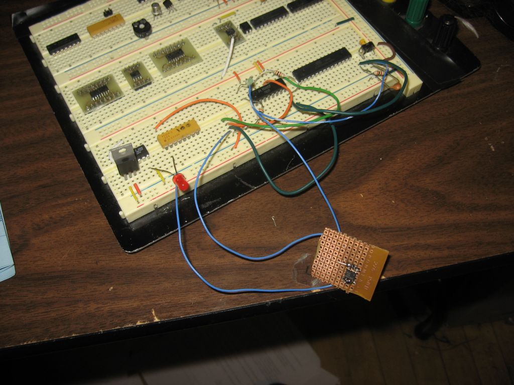
So, at TomG’s suggestion I am adding a CMOS J-K Flip-Flop to the mix. I don’t have the final design down just yet but I did breadboard up an early prototype. In the circuit pictured above, J and K are held high and Q goes to the gate of the power MOSFET and a 3K bleed off resistor. The button goes to the clock-in to toggle the state of Q.
The Flip-Flop power itself is not switched. Its hot all the time. The lowest setting on my multimeter is 200 uA. I was not able the detect any current draw at that level. Earlier I tried to used a bi-polar PNP transistor to fix my woes but I was only able to get down to minimum current of 200uA and a 0.67 voltage on the MOSFET gate. So, I think the J-K will be a winner
As of now circuit will properly switch the 5V regulator and MCU from the button with a only a small amount of button stickiness due to my weak debounce circuit, a 10nF cap in parallel with a 3K resistor to ground. The next step is to integrate the MCU into the power control. I may be able to take over clock control and just have the button force power to the MCU long enough to have the MCU pop the clock until it sees a High on Q.
I’ll give that concept a go next time.