Arduino-Powered Surround Sound Synthesizer

The Makerspace Eight Speaker Super Surround Sound System(MESSSSS) has been supplying music to the Makerspace for quite a while now, but I identified a problem even before the system was fully installed.  Stereo recordings played back on two speakers are great if you’re in the “sweet spot.” If not, traditional approaches to 5.1 audio improve things, but all rely on there being a single “front of the room.” Unfortunately, it’s not clear which side of the 3000 square foot Makerspace shop is the front, and with four pairs of speakers in the room, even stereo imaging is difficult.

Fortunately, I’ve just completed the Makerspace Eight Speaker Super Surround Sound System’s Enveloping Surround Sound Synthesizer (MESSSSSESSS).  The MESSSSSESSS takes stereo recordings and distributes sound to the eight speakers in an entirely fair and user configurable way, thereby eliminating the need for a “front of the room.” Now listeners can be arbitrary distributed throughout a room, and can even be oriented in random directions, while still receiving an enveloping surround sound experience!

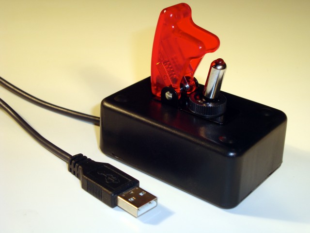
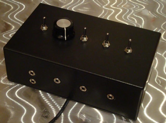
The MESSSSSESSS user interface is somewhat simpler than most surround sound processers, as it consists of only four switches and one knob.  Somewhat inspired by StrobeTV, the simplest mode references questionable quadraphonic recordings, in that the music travels sequentially from speaker to speaker, chasing around the room either clockwise or counterclockwise at a rate selected by the knob. With the flip of a switch, sound emanates from the eight speakers in a random order. Things get considerably less deterministic after flipping the Chaos Switch, adjusting the Chaos Knob, and entering Turbo Mode:  Its best to visit Milwaukee Makerspace to experience the madness for yourself.  I’m legally obligated to recommend first time listeners be seated for the experience.

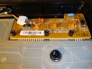
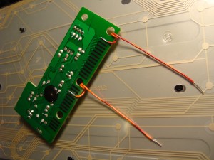
The MESSSSSESSS is powered entirely by an Arduino Uno’s ATmega328 that was programmed with an Arduino and then plugged into a socket in a small, custom board that I designed and etched at the Makerspace.  The ATmega328 outputs can energize relays that either do or don’t pass the audio signal to the four stereo output jacks.  Care was taken to use diodes to clamp any voltage spikes that may be created as the relays switch, thus preventing damage to the ATmega328 outputs.

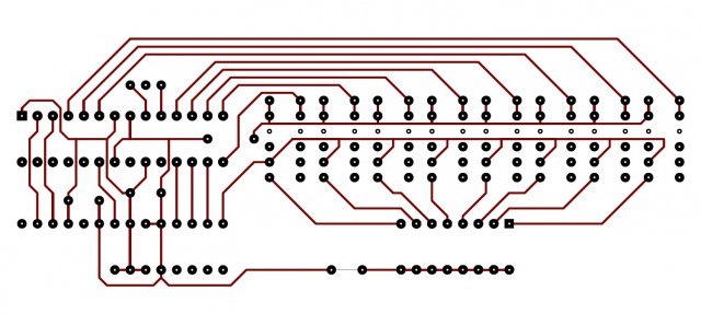
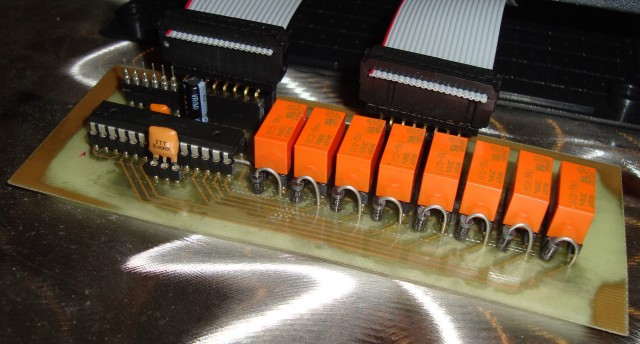
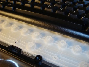
As shown by the minimal part count above, using the ATmega328 “off the Arduino” is quite easy:  Just connect pins 1 (The square one), 7 and 20 to 5 volts, and connect pins 8 and 22 to ground.  Then, add a 22uF cap and small bypass cap between power and ground, and a ceramic resonator to pins 19 and 20.  You can even use an old cellphone charger as the power supply.  Boom.  That’s it.  The real benefits of making your own boards are having a well integrated system, and cost, as the Atmel chip is $4.50 while a whole Arduino is $30.  Also visible in the photo are a programming header and the two ribbon cables that route all the signals to and from the board.

A Simple Aux Input For iPod Speaker Systems

The first generation of Bose SoundDocks did not feature an aux input jack, they are only compatible with the 30 pin connector of iPods and iPhones.  Lately, my music player of choice is my Droid Razr, which has 60+ Gb of music on it, even more in the cloud, and no 30 pin connector.  I decided to add an auxiliary input to my SoundDock in the easiest and quickest way possible. I made an adapter cable using half of a $6 iPod extension cable, half of a $1 3.5mm headphone cable, and two necessary resistors.  I can plug this adapter cable directly into any unmodified SoundDock, or any other amplified speaker system that has a 30 pin connector.

It turns out that the SoundDock is smart, and will only power on when it senses 3.3VDC on pin 18 of its input connector.  Luckily, it also outputs 12VDC on pin 19 to recharge the attached iPod’s battery.  To trick the SoundDock into turning on with no iPod attached, I made a voltage divider by soldering a 20 Kohm resistor between the wires connected to pins 18 and 19, and a 4.7 Kohm resistor between the wires connected to pins 18 and 1.  The voltage between pins 18 and 1 was measured to be ~3VDC, which isn’t 3.3VDC, but is sufficient to power up the SoundDock.  I soldered the three pins of the 3.5mm headphone jack to the 30 pin connector’s wires as follows: Ground to pin 1, right audio to pin 3 and left audio to pin 4.  I used 1206 surface mount resistors because they measure only 3.2mm by 1.6mm, a size which fits conveniently under the shrink wrap joining the two cables.  The most time consuming part of this two hour project was identifying which color wires were connected to pins 1,3,4,18 & 19, and determining if the pin on the left of the photo was #1 or #30.

The Critic

This is “The Critic.” It’s the USB accessory version of a red pen: Once armed by rotating the red safety cover up, the device is activated by simply flipping the toggle switch.  When connected to a computer via the convenient USB plug, it will begin to delete text, continually deleting until all the (presumably erroneous) text preceding the curser has vanished. At that point, the safety cover can be lowered, thereby deactivating the device.  The Critic is an indispensable tool for use when the document you’re editing is just so full of errors that your fingers begin to ache from holding down the delete key.  The Critic measures 3″ by 2″ by 2″ tall, and was designed to fit conveniently within arm’s reach, beside your keyboard or mouse.

I was inspired by the open source work of Pete at RasterWeb! and his recent effort to bring “The Button” to a wider audience of busy or non-makers.  He has freely helped tens of people create their own buttons, but is now able to fulfill requests for preassembled units. Among other applications, these USB buttons can be used as the shutter control of  Mac powered Photo booths at public events. These photo booths are powered by Sparkbooth, which can automatically upload the photos to Facebook, Twitter, tumblr or other social media sites.  His buttons emulate a keyboard, and contain an Arduino Teensy (only 0.7″ by 1.2″), which is a USB based AVR microcontroller.  Despite the Teensy cost of $16, I saw an opportunity for cost savings by opening a standard USB keyboard and spending a few minutes to extract and reverse engineer their compact circuit board.  Although this isn’t a solution suitable for even small scale production, it can work for a one-off prototype, like The Critic.

Below are several photos that show the process of opening the keyboard to extract and modify the circuit board.  When the top of the keyboard is removed, a sheet of silicone ‘popples’ is revealed.  These ‘popples’ are the springs under each of the keys.  Under this layer are two sheets of thin plastic, one with conductive ink traces that are (mostly) horizontal, and one with conductive ink traces that are (mostly) vertical.  These layers of traces are separated by a small gap.  When a key is pressed, a protrusion on the bottom of that key’s popple pushes the two layers of plastic together at this location: connecting one of the vertical traces to one of the horizontal traces. These traces are routed to the circuit board via a row of contacts under the front edge:


The chip (under the black epoxy potting on the bottom of the board) detects this electrical connection, and outputs the appropriate character over the USB cable.  The keyboard, popples and plastic layers can all be replaced by an external switch and wires soldered directly to the circuit board.  The photo below shows wires (whose free end is to be connected to the switch) soldered to the pads required to output a space bar character.  To output other characters, simply follow the vertical and horizontal traces to the board, and solder wires to those pads instead.


RasterWeb! approves of this message.