Rubens Tube Update!

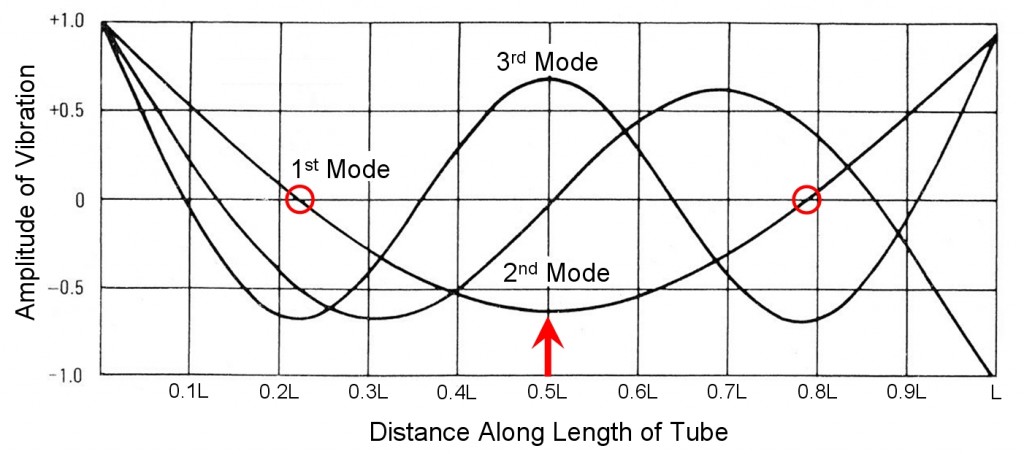
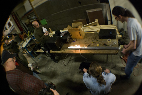
The Rubens tube I made a while back puts on a fairly impressive show when its speaker is driven with music or a noise box, as was done during the Milwaukee Makerspace Grand Opening.  The story is somewhat different when it is used to display the acoustic standing wave pattern inside the tube.  When a single tone (sine wave) at a resonance frequency of the system is played though the speaker, the heights of the flames map out the sinusoidal shape along the length of the tube. There are two very important variables whose values determine how well this will work.  These are the acoustic pressure in the tube, which is set by the speaker and its input voltage, and the propane gas pressure, which is set by a regulator or the valve on the propane bottle.  Even a professionally made Rubens tube has a relatively small range of these two pressure settings that create a nice sine wave distribution of flame heights.

After running my Rubens tube for a short while, I realized I’d made a few design choices that make the already small range of good operating parameters even smaller.  First, I didn’t actually use a gas regulator, I only used the valve on the propane nozzle.  Note that the propane flow rate is highly affected by the temperature of the nozzle, so the propane tank must be kept in a water-filled bucket to prevent the outlet valve from freezing up.  Just like a gas pressure regulator can be used, so could an acoustic pressure regulator (i.e. a compressor).  This could help prevent the flames from extinguishing during particularly dynamic musical passages.  Alternately, some type of pilot light system could be devised so that the flames automatically relight – perhaps glowing red nichrome wire could be added in a moderately safe way.  I also spaced the fifty 0.043” diameter holes apart by only 0.9 inches.  Having this many holes reduces the amplitude of the resonances, making them more difficult to ‘find’ by simply listening to the amplitude when adjusting the frequency input to the speaker.   Better performance would be achieved by having fewer holes spaced further apart.  Lastly, I’ve used a pipe whose inner diameter is only 2.5 inches.  A larger diameter pipe would further increase the amplitude of the resonances.

I put an electret microphone inside the Rubens tube at the end opposite the speaker, and measured the pressure inside while electrically driving the speaker with pink noise.  I did this with both air and propane inside the tube.  The following graph shows the low amplitude of the tube’s resonances with propane inside — between 4 and 7 dB.

The other interesting bit of data one can find from this graph is the speed of sound in propane.  Knowing the sound speed, one can calculate either the length of pipe needed to have a particular fundamental resonance frequency (n=1) or if a particular speaker has a resonance frequency low enough to excite the fundamental resonance of a particular length Rubens tube.  The resonance frequencies of a tube having uniform cross sectional area and two rigidly closed ends are given by: Fn = nC/(2*L), where n is the nth mode, C is the sound speed, and L is the length of tube.  The Rubens tube doesn’t have two closed ends, it has a paper cone speaker at one end.  It also doesn’t have uniform area – it has a small open volume in front of the speaker.  Both of these will change the “effective” length of the tube.  Don’t worry though, we can use the measured resonance frequencies with air in the tube to calculate the effective length: Leff = nC/(2*Fn).  Knowing C=343 m/s in air, we can use the measured resonances of the first three modes  (144 Hz, 262 Hz and 380 Hz) to find that the (averaged) effective length is 1.28m.  Using this effective length and the lowest three resonance frequencies (108 Hz, 205 Hz, and 300 Hz) with propane in the tube, Fn = nC/(2*Leff) predicts the sound speed to be ~265 m/s.

Makerspace members or any other folks near Milwaukee should feel free to stop by (on Tuesdays or Thursdays evenings) and fire up the Rubens tube.  Just use a small amplifier so you don’t put more than 30 Watts into the 4” speaker!  For some scholarly information about Rubens tubes, check  out the series of articles in the journal “The Physics Teacher:”  M. Iona (14), p325 from 1976; T. Rossing (15), P260 from 1977; R Bauman (15) p448 from 1977; and G. Flicken (17) p306 from 1979.

Audio Switch Boxes!

I was recently comparing several powered speaker systems, but didn’t like the audible *Pop* I heard when plugging and unplugging the 3.5mm headphone jack into each of them.  I made a switchbox that eliminates this pop by switching the one input (my mobile phone) to any of the four outputs.  I didn’t have the right rotary switch at the time I built it, so it actually has two knobs that select where the input signal goes, meaning I can have two systems playing at the same time.  Alternately, the box can be used to switch either of two inputs selected with one knob to either of two outputs selected with the second knob.  Even more alternately, the box can be used to switch four inputs to a single output.

I few days later, after I purchased(!) the correct rotary switch, I built a second switch box.  This one has stereo logarithmic-taper potentiometers wired as voltage dividers, effectively acting as independent volume knobs on each channel.  With these volume controls, the playback levels of speaker systems with different gains can be matched, for ease of comparison.

Giant, Ominous Wind Chimes

A while back I bought five 4.5 foot long aluminum tubes because the price was so low that I couldn’t resist.  They are 3.25 inches in (outer) diameter, and have a wall thickness of 0.1 inches.  Recently, I decided to make them into the longest and loudest wind chimes I’ve ever heard.  The longest tube rings for over a minute after being struck by the clapper.  After thinking for a while about which notes I should tune the tubes to, I found that fairly large chimes are commercially available, but they are tuned to happy, consonant intervals.  I consulted a few musically savvy friends (Thanks Brian and Andrew!) to gather some more ideas for interesting intervals on my chosen theme of “Evil & Ominous.” I ended up with quite a few ideas, and with Andrew’s help, I sampled the sound of the longest tube being struck, and recorded mp3’s of each set of notes to simulate the sound of the chimes ringing in the wind.  I ended up with something delightful: D4, G#4, A4, C#5 and D5 (which are 294 Hz,  415 Hz, 440 Hz, 554 Hz, and 587 Hz).  That’s right, there are two consonant intervals (octave and major 5th), but look at all those minor seconds and tritones: Delightfully Ominous!

Then the science started:  How to determine the tube lengths to achieve the desired notes?  How to suspend the chimes so they sound the best, and are the loudest?  Where should the clapper strike the chimes in order to produce the loudest sound or the best timbre?

Wind chimes radiate sound because they vibrate transversely like a guitar string, not because they support an internal acoustic standing wave like an organ pipe.  Pages 152 & 162 of Philip Morse’s book “Vibration and Sound” show that the natural frequencies, v, of hanging tubes are given by the following expression:

Pretty simple, right?  One only needs to know rho and Q, the density and Young’s modulus of aluminum, l, the length of the tube, a & b, the inner and outer radius of the tube, and the beta of each tube mode of  interest.  Don’t worry though, there is a simpler way.  If all of the tubes have identical diameter and are made of the same material (6061-T6 Aluminum!), the equation indicates that the natural frequency of a hanging tube scales very simply as the inverse of the tube length squared.

Using the above relationship (frequency ~ 1/(length*length)) to compute the ratios of tube lengths based on the ratio of frequencies produces:

Length of D4 tube = 1.000 * Length of D4 tube

Length of G#4 tube = 0.841 * Length of D4 tube

Length of A4 tube = 0.817 * Length of D4 tube

Length of C#5 tube = 0.728 * Length of D4 tube

Length of D5 tube = 0.707 * Length of D4 tube

The longest tube is 133.1 cm (52.40 inches) long, so all the tubes were scaled relative to it.  Note that the frequencies are slightly different than the notes I was aiming for, but absolute pitch is only a requirement when playing with other instruments.

~D4 = 293.66 Hz = 133.1 cm = 280.3 Hz

~G#4 = 415.3 Hz = 111.9 cm = 396.4 Hz

~A4 = 440.0 Hz = 108.7 cm = 420.0 Hz

~C#5 = 554.37 Hz = 96.9 cm = 529.1 Hz

~D5 = 587.33 Hz = 94.1 cm = 560.6 Hz

How accurately do these tubes need to be cut?  For example, how important is it to cut the tube length to within 1 mm?  This can be calculated simply, using the above equation.  A length of 108.7cm gives 420.0 Hz, whereas a length of 108.8cm gives 419.23 Hz.  This spread is 0.67 Hz, which is a fairly small number, but these small intervals are often expressed in cents, or hundredths of a half-step.  This 1 mm length error gives a frequency shift of 31cents.  Does this matter?  Well, the difference in pitch of a major third in just and standard tuning is 14 cents, which is definitely noticeable.  It is preferable to be somewhat closer than this 1mm, or 2/3 Hz to the target interval.

The tubes were rough-cut to 2 mm longer than the desired length on a bandsaw to allow the ends to be squared up in case the cut was slightly crooked.  The resonance frequency was then measured by playing the desired frequency from a speaker driven by a sine wave generator with a digital display.  I then struck the tube and listened for (and counted) the beats.  If two beats per second are heard, the frequency of the tube is 2 Hz different than the frequency played through the speaker.  With this method using minimal equipment, I quickly experimentally measured the resonance frequency to less than 0.5 Hz (one beat every two seconds), which is ~10 cents.  I then fine tuned the tube length using a belt sander, and measured the resonance frequency several times while achieving the correct length.  In reality though, if I missed my target lengths I’d only be adding a little more beating and dissonance, which might have only added to the overall ominous timbre.

How to suspend the tubes?  Looking at the mode shapes of the tube for guidance, I suspended the tubes by drilling a hole through the tube at one of its vibrational nodes, and running a plated steel cable through it.  Check out the plot below from Blevins’ New York Times Bestselling book “Formulas for Natural Frequency and Mode Shape.”

This plot shows a snapshot of the tube’s deflection as a function of position along the tube.  Imagine that the left side of the tube is at 0, and the right side of the tube is at L.  This plot shows the first three mode shapes of a “straight slender free-free beam,” which my 1.33 meter long, 83mm diameter tube qualifies as.  Just like a guitar string, this tube has multiple overtones (higher modes, or harmonics) that can be excited to varying degree depending where the clapper strikes the tube.  The guitar analog of this is the timbre difference one hears when picking (striking) the string closer to or further from the end of the string (the bridge).  This plot also shows where the tube should be suspended – from the locations where the tube has no motion in its first, fundamental mode.  Those two places, a distance of 0.221L from the tube’s ends, are circled in red.  When striking the tube suspended from either of these locations, the tube rings the loudest and for the longest time duration (as compared with any other suspension location).  Similarly, when striking the tube in the location noted by the red arrow (the midpoint of the tube), the tube rings the loudest.  I won’t get into more math and fancy terms like “modal participation factor,” but it is true that suspending the tube from the circled red locations also results in the lack of excitation of the third mode (which has a motional maximum at this location).  Similarly, striking the tube at its midpoint results in the lack of excitation of the second mode, due to its motional minimum at this location.

Thanks to David for the Ominous Photo.   An Ominous Chime video will soon follow.

Redwood Audio Amplifier

A few months ago I started collaborating with Jordan Waraksa on a project that is currently on display at the Haggerty Museum of Art, in a show running until the end of December.  He sculpted a pair of wooden acoustic horns called Bellaphone 5 & 6 out of walnut.  Each horn rests on a redwood base that houses a small speaker.  If you visit the Haggerty, you’ll hear the speakers playing songs by Jordan’s band, The Vitrolum Republic.  If you really love the Bellaphones and amplifier, know they are for sale.

I developed and built the electronics for the horn’s amplifier, whose chassis Jordan also sculpted from redwood.  Because the chassis is wood and has no vents (for aesthetics), electrical efficiency became a high priority in order to prevent overheating.  I chose to use a Maxim 98400A class D amplifier driven by a high efficiency switching 15V DC power supply.  I added a digital signal processing chip from Analog Devices to increase the bandwidth of the horn and smooth out its frequency response (i.e. to improve the audio fidelity).  Analog’s ADAU1701 is a remarkably powerful chip – it is more than capable of these tasks.  In addition, the 1701 prevents bass notes (frequencies below 100 Hz) from reaching the small speakers (which are incapable of reproducing these low notes), which would otherwise emanate from the horns as distortion.  Finally, the 1701 also adds a small amount of compression, which prevents distortion at the loudest output levels.   The 1701 is actually real-time programmable via a USB connection to a computer running Analog Device’s free SigmaStudio software.  It’s a tremendously user friendly GUI environment with drag and drop audio processing blocks.

Check out the inside of the amplifier as it was being assembled, prior to the addition of many ferrite beads which eliminate the audible noise from the three high efficiency switching power supplies:  One powering the amp, one powering the DSP board, and one continuously charging a Motorola Cliq XT handset playing songs from the Vitrolum Republic.

Here are two more close ups, one of the amplifier:

And one of Bellaphone five and six:

Rubens Flame-Tube

Last Saturday morning I spent 4 hours making a Rubens Tube at the Makerspace while the crew from Pumping Station: One was shooting footage for their documentary entitled The Rebirth of the Maker Movement. Here is the first lighting of the tube:
Milwaukee Makerspace: We play with fire
A Rubens Tube is a pretty flashy piece of physics demo gear that uses fire to show the acoustic standing wave pattern inside an organ-pipe like tube fitted with a loudspeaker at one end. The 48” long, 2.5” diameter tube is filled with propane, which escapes through a series of 50 0.043” diameter holes spaced by 0.9 inches all along the length of the tube. Once the tube is full of propane (with absolutely no air), the 50 propane jets are lit with a striker or match, and all 50 flames have an identical height of 2 or 3 inches. When sound is played though the speaker at one end of the tube, the flame height is modulated by the acoustic pressure from the speaker. When a single tone (sine wave) at a resonance frequency of the system is played though the speaker, the heights of the flames map out the sinusoidal shape along the length of the tube. Playing music with dynamics or signing through the speaker is especially dramatic. I need to spend a few more hours fitting the Rubens Tube with a speaker at the other end and adding an additional propane inlet.