My sister is a Theater Manager at the Patel Conservatory in Tampa, FL. About two weeks ago she texted me and asked if I could make her a prop she needed for an upcoming production. “How keen would you be on making me a mirror for “Beauty and The Beast,” she said. “They want a mirror that lights up and sparkles like the one from the movie.” Even with limited experience just tinkering around, I knew I could do something fairly easily, so I agreed and got to work.
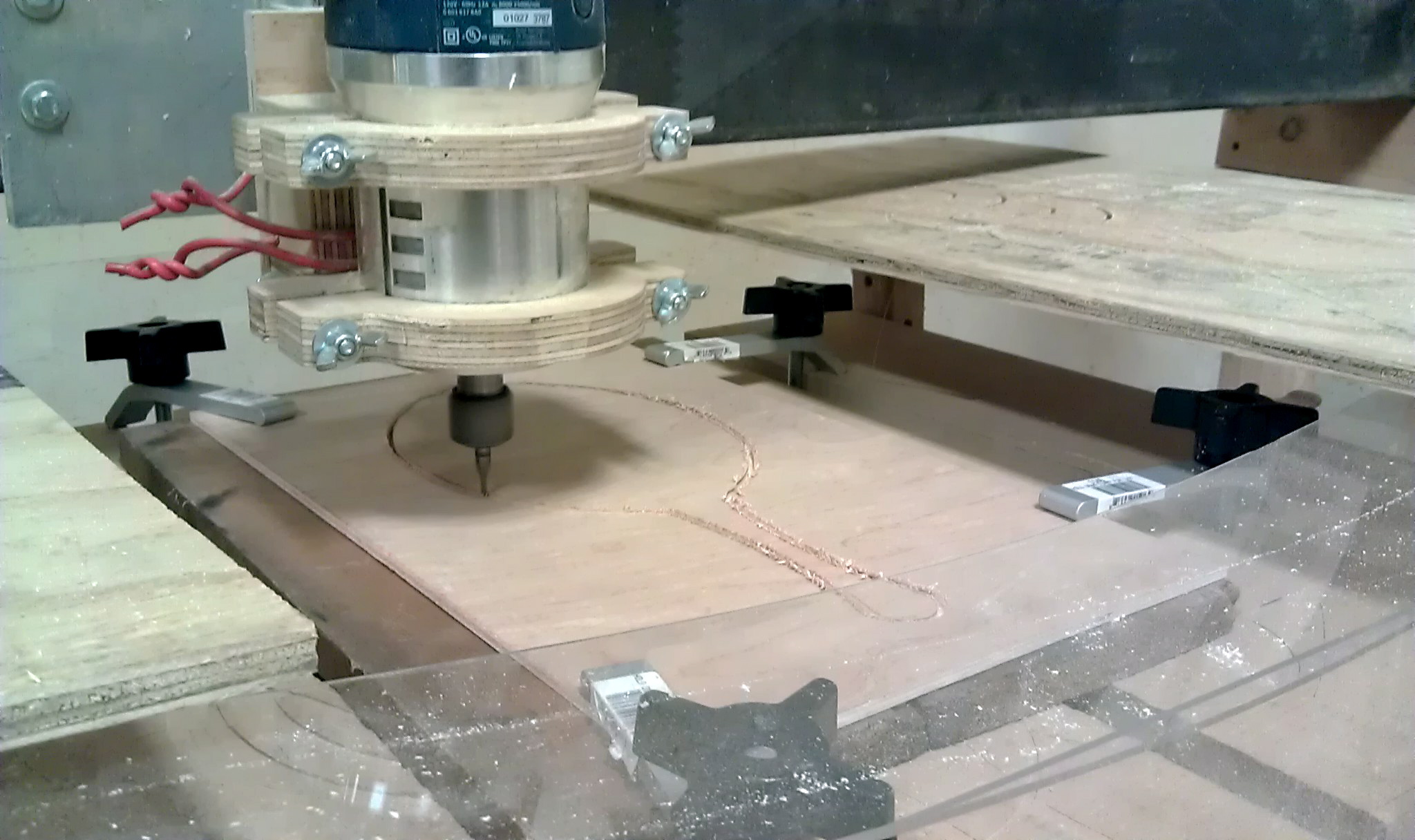
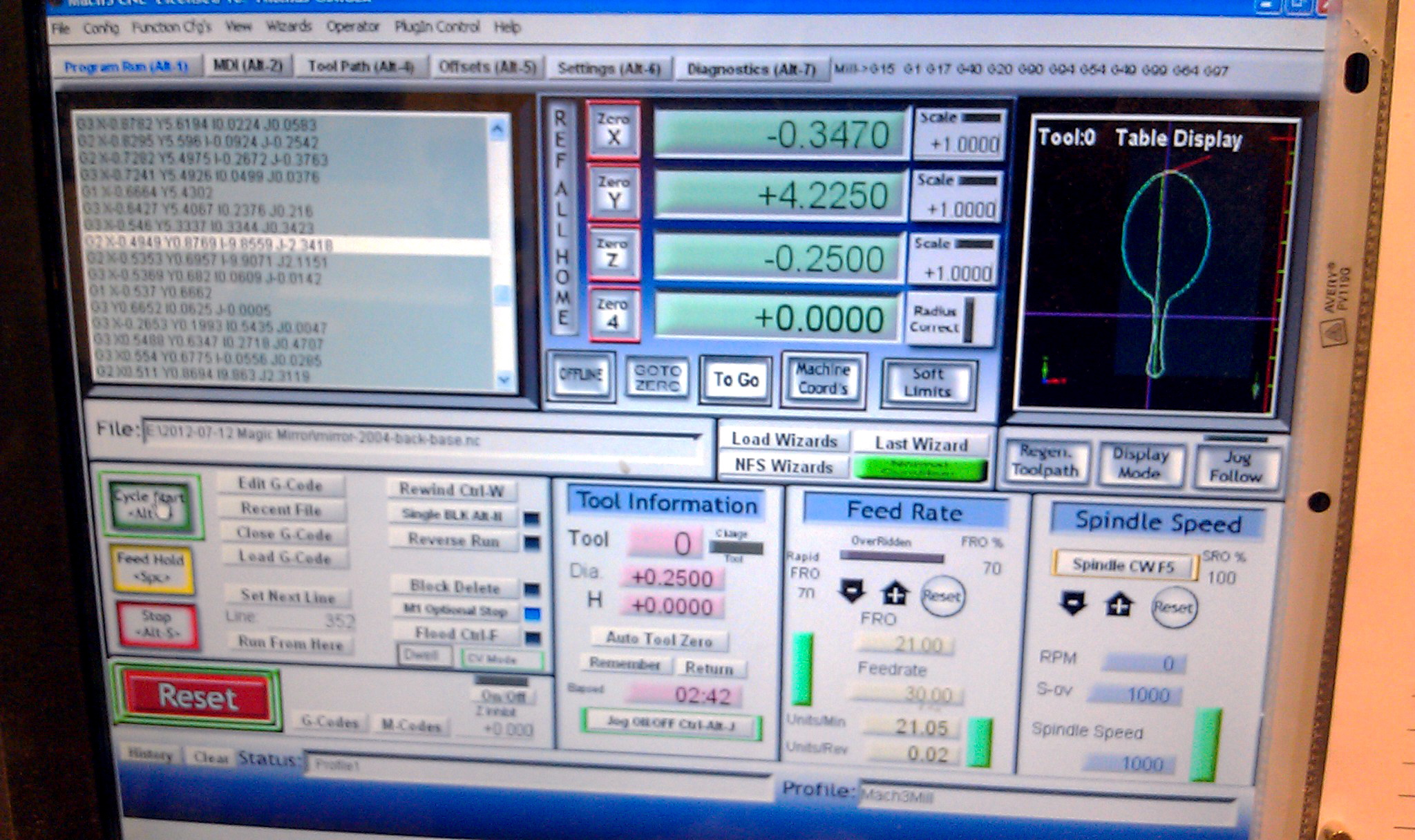
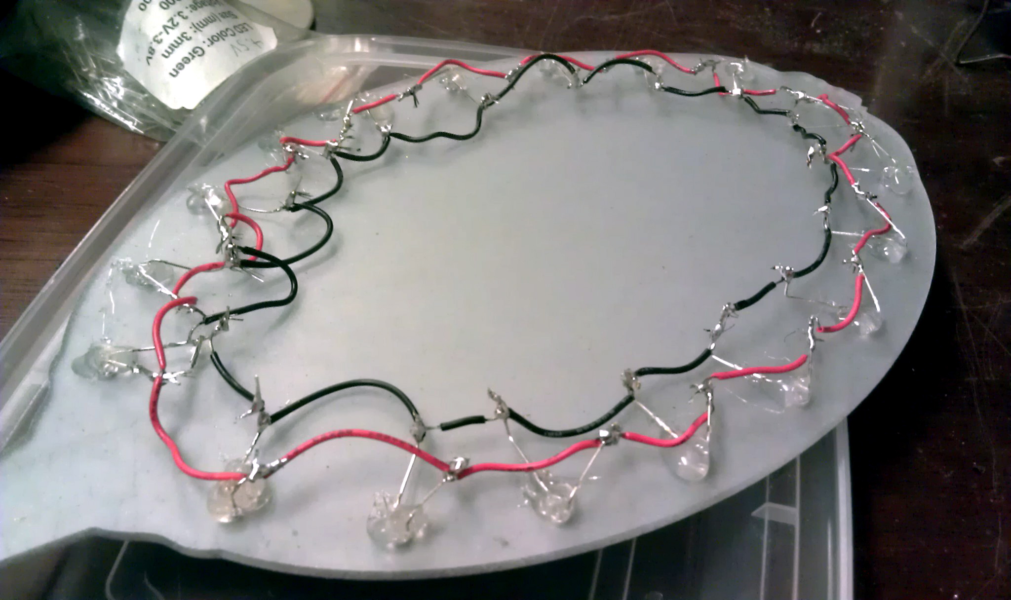
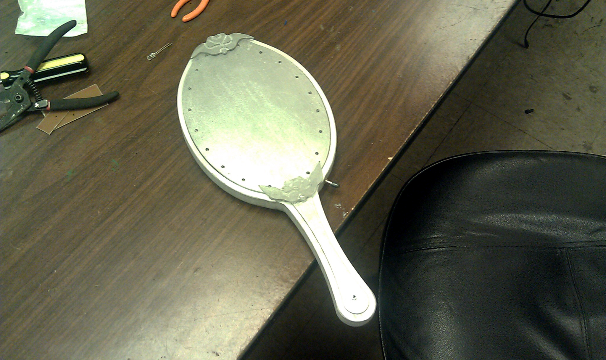
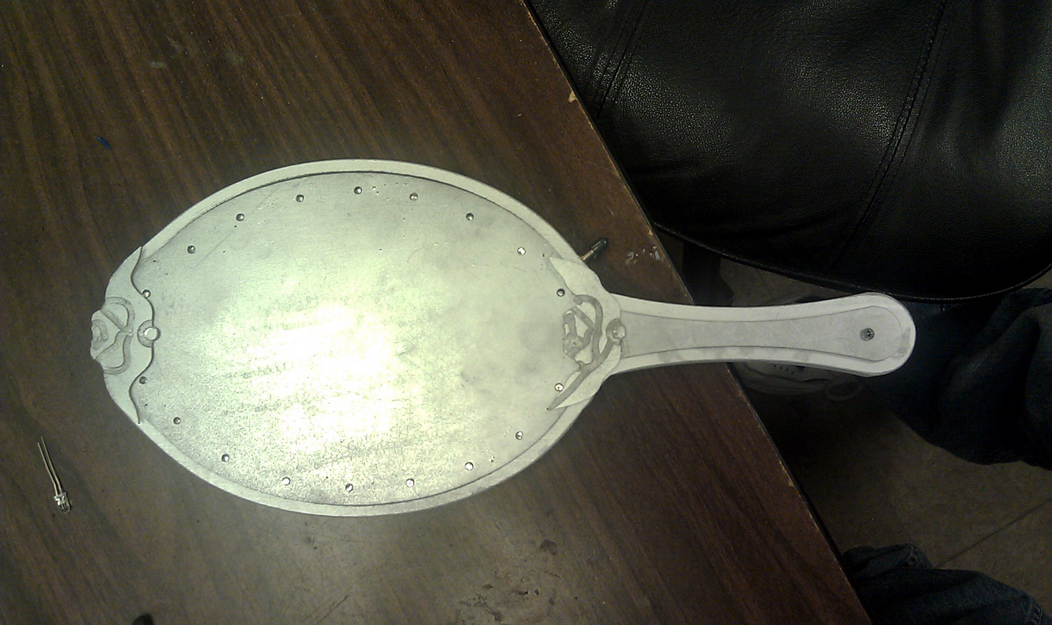
I combined two different circuits (a 555 timer to flash and a RC circuit to fade) and built a wooden frame with acrylic plates for the front and back. The wood and plastic were CNC-milled, then sanded and painted before the electronics were installed and glued into place.
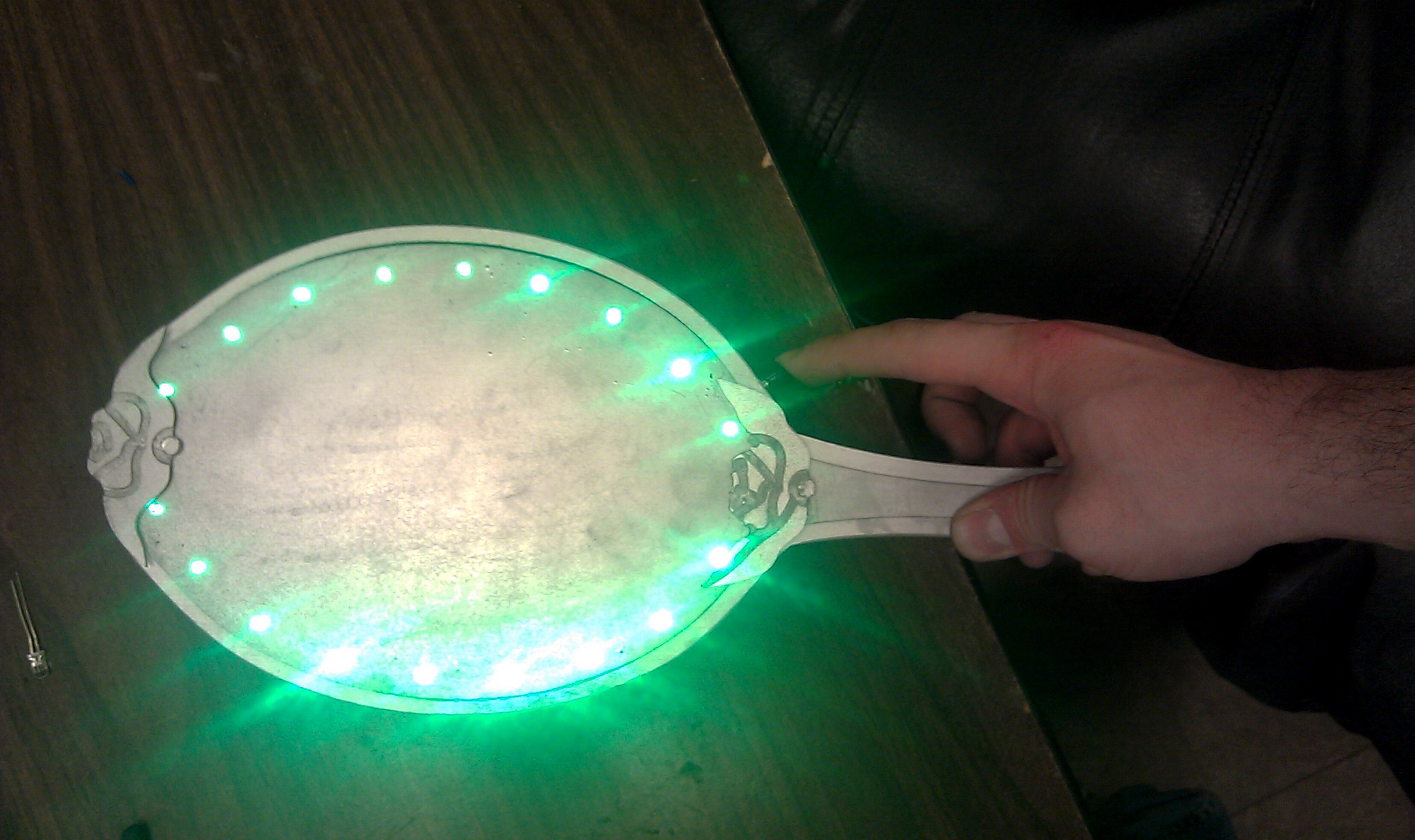
The result was a fairly decent-looking, shiny, light-up hand mirror with a small thumb button on the right side that flashes 16 bright green LEDs when pressed. It all runs off a single 9-volt battery and the back can be unscrewed to replace it should it ever die.
Total build time from start to finish was probably close to 15 hours over the course of one week. The play was Thursday, July 19th and from what I’ve heard, it was a great success. I’ll add pictures from the performance if I get some.
Yeah. Having access to a laser cutter is pretty boss. I’m planning to wear this to the premiere of a certain movie this weekend. Four layers of acrylic; two diffuse, two opaque. 11 LEDs, 11 100 Ohm resistors, some phone cord, some solder, and a 9V battery. There’s no lack of great pages on Instructables about how to make your own.
When I arrived at the space Sunday, I had planned to work on a circuit board design in DipTrace. After I left, I had spent six hours rewiring a golf cart. Allow me to explain…
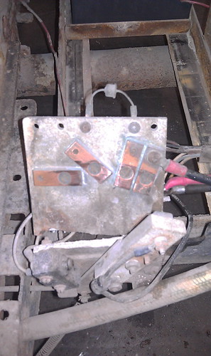
It all started when I went to take the trash out. I used the golf cart with the flatbed to ferry the cans out to the dumpster. After emptying the cans, I rode back and decided to charge the cart’s batteries. Tom and Rich had just returned from lunch and Tom suggested we swap out batteries instead. While swapping them out, we decided to also rewire them. While rewiring them, part of the cart broke. There’s a small white plate under the driver’s seat. It’s about 4″ x 6″, likely made of asbestos, and holds a series of copper contacts that a lever attached to the gas pedal slides over to select the speed of the cart. And it broke in two when we tried to tighten fix a wire on it.
We had a few options: try to mend the old, brittle plate, replace it with something new, rewire the whole thing, or scrap everything out for a solid state motor controller. Not wanting to adopt a new project or sacrifice a motor controller that could be better used elsewhere, I volunteered to try and fabricate a replacement for the broken part.
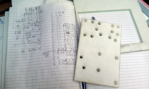
First I documented everything just the way it was. I labeled wires, took photos, scribbled down notes, etc. Next I went about removing the broken plate. There was probably more rust than metal on those bolts. Then I took a pair of digital calipers and a ruler and measured the locations and sizes of holes for each component. I considered using the CNC router or drilling a plate by hand, but the laser cutter seemed to be a much faster and precise approach. I drew up my replacement plate in CorelDraw and found a scrap of 1/4″ acrylic that matched the size and thickness of the old plate. After some tinkering with the printer driver and a dozen passes with the laser, I had a copy of the original in plastic form.
The next few hours were spent migrating the old parts over to the new one and wiring it back in. Right around 7:00 PM, I tied some batteries together and the thing leaped forward. A few more tests and it should be as good as new. Someone suggested that maybe the plate was asbestos to avoid heating issues so we’ll keep an eye on that too.
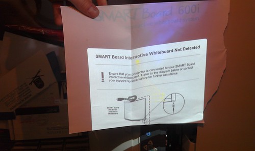
Back in August, Tom acquired several Smartboard-brand projectors and was interested in getting them to work as a normal projector would. As you may recall from my original post on this project, these projectors will not display anything other than an error screen without their accompanying interactive whiteboards connected.
The original approach was to simply substitute my own video signal by swapping out some cables. There is a dual-link DVI cable that attaches to the projector lamp assembly through the telescoping neck of the projector to its wall-mounted computer base, the Unifi 35. I tried simply connecting a computer to the DVI connection on the lamp, but the lamp wouldn’t power on. We eventually surmised that the lamp and the Unifi 35 were communicating somehow through the DVI cable and the lamp wouldn’t power on unless the computer detected that it was attached. Computers with DVI connections have the ability to detect when display devices are connected as well as instruct them to power on or off.
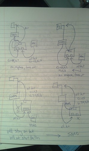
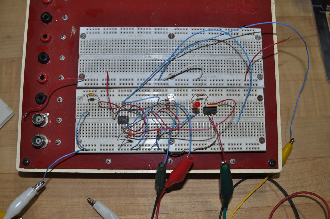
That led to trying to swap out individual pins in the cables. I built three DVI breakout boards and set up a breadboard so I could mix and match pins from two sources and combine them to send on to the projector lamp. I tried using the digital pins from my own source (a G5 Macintosh) and the analog pins from the Unifi 35. After a lot of trial and error, it seemed the projector was communicating with the Unifi 35 somehow using either the analog pins on the DVI connection, the second digital link, or both. Also, it seemed I could disconnect some pins after the projector was powered up, but I couldn’t start without them. It looked something like this (table copied from Wikipedia):
Pin
Description
Purpose
Required?
1
TMDS data 2−
Digital red− (link 1)
Required at all times
2
TMDS data 2+
Digital red+ (link 1)
Required at all times
3
TMDS data 2/4 shield
Required at all times?
4
TMDS data 4−
Digital green− (link 2)
Required at all times?
5
TMDS data 4+
Digital green+ (link 2)
Required at all times?
6
DDC clock
Required at startup only
7
DDC data
Required at startup only
8
Analog vertical sync
Required at startup only?
9
TMDS data 1−
Digital green− (link 1)
Required at all times
10
TMDS data 1+
Digital green+ (link 1)
Required at all times
11
TMDS data 1/3 shield
Required at all times?
12
TMDS data 3-
Digital blue− (link 2)
Required at all times?
13
TMDS data 3+
Digital blue+ (link 2)
Required at all times?
14
+5 V
Power for monitor when in standby
Not required?
15
Ground
Return for pin 14 and analog sync
Not required?
16
Hot plug detect
Not required?
17
TMDS data 0−
Digital blue− (link 1) and digital sync
Required at all times
18
TMDS data 0+
Digital blue+ (link 1) and digital sync
Required at all times
19
TMDS data 0/5 shield
Required at all times?
20
TMDS data 5−
Digital red− (link 2)
Required at all times?
21
TMDS data 5+
Digital red+ (link 2)
Required at all times?
22
TMDS clock shield
Required at all times?
23
TMDS clock+
Digital clock+ (links 1 and 2)
Required at all times?
24
TMDS clock−
Digital clock− (links 1 and 2)
Required at all times?
C1
Analog red
Required at startup only
C2
Analog green
Required at startup only
C3
Analog blue
Required at startup only
C4
Analog horizontal sync
Required at startup only
C5
Analog ground
Return for R, G, and B signals
Required at startup only
After a lot of trial and error, I didn’t seem to be much closer to the goal of getting my own video source to display. I also began to consider that the manufacturer may have switched around some pins between the Unifi 35 and the projector to prevent consumers from servicing the unit. The DVI cable I was working with was internal to the machine after all. There’s no reason any one would ever try to connect their computer’s DVI output to the lamp itself. Signals leaving the Unifi 35 could be sent on a different pin than the DVI standard suggests and then rearranged back into the standard configuration at the lamp assembly. I never really dismissed that possibility, but I also didn’t see much to support it.
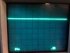
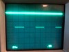
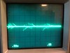
I trudged on and hooked up an oscilloscope to monitor was was going on with the analog pins, C1 through C5, because they seemed to be critical to the lamp turning on, but not necessarily staying on. This is what I found:
Pin
Description
In Standby Mode
Once Powered On
C1
Analog red
0v constant
+3.3v constant:
C2
Analog green
+5v constant
+5v constant for 0.93 seconds every second then a brief flash for 0.07 seconds of this waveform:
+5v (58% of the time)
0v (42% of the time)
at ~1.2 kHz
C3
Analog blue
+5v constant
+5v constant for 0.93 seconds every second then a brief flash for 0.07 seconds of this waveform:
~0v and a more complex pattern (0.8 ms/3.5 ms)
+5v (0.8 ms/3.5 ms)
~0v and a more complex pattern (1.1 ms/3.5 ms)
+5v (0.8 ms/3.5 ms)
at ~285 Hz
C4
Analog horizontal sync
0v constant
0v constant for 0.93 seconds every second then a brief flash for 0.07 seconds of this waveform:
C5
Analog ground
Reference for all
Reference for all
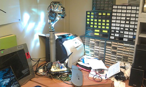
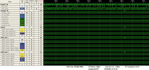
Unsure of what these signals represented, I consulted with Royce, Tom, and a few others and worked up the courage to use a logic analyzer for the first time. Most of the work was wiring the thing up and assigning names to the leads in the software. My breakout boards turned out to be more fragile than I expected so I ended up resoldering a all of the flaky connections. The Intronix 34-channel Logicport Analyzer is pretty slick and comes with some great software tutorials. Once I got it going, it was fairly straight forward. I can definitely see how this device can come in handy now that I’ve used it.
One of the first problems I ran into was the multitude of different voltages at work. The Logicport software has a logic voltage threshold setting to help weed out logic from other signals, but I found myself dealing with signals less than 0v, as well as +3.3v, and +5.0v. I eventually scanned the spectrum and sat, clicking the threshold up in small intervals of 0.05v, and watched to see if anything appeared on the screen. It would seem that while in standby mode, some of the the TMDS data pins and the DDC clock and data pins are held above +2.0v. Around 0.0v, some of the data shields show some variation between low and high during standby but as the projector is starting up, there are definite patterns on TMDS data shields 2/4, 0/5, and the clock shield. TMDS link 1 shows some activity during startup in the +3.3v range and then shortly after link 2 does as well as the analog red pin. Why a digital signal might appear on the analog pin is unclear. I could be measuring it wrong also, but there does appear to be a signal there. I also checked the analog pins during standby against what I saw with the oscilloscope and the numbers seem to agree except that the C4 horizontal analog sync pin showed voltage at or above +2.00v with the analyzer when the oscilloscope showed no voltage difference at all.
Since I was more interested in the control data than the video data, I focused my attention to the DDC clock and data pins to see if I could decipher how the projector and Unifi 35 were talking to each other. PC monitors and projectors with DVI connections use a display data channel (DDC) and a standard called I2C (I squared C). I found some great information on I2C and DDC protocols online here and here. At +5.00v I read a portion of the communication between the Unifi 35 and the projector and tried to analyze it. Unfortunately, the data doesn’t seem to follow what I’ve read on the I2C standard. The clock rises and falls unexpectedly, the start/stop commands don’t appear where I would expect them to, nothing resembles a 7-bit device address and there is seemingly no pattern to data. The other logic analyzer screenshots can be found here.
We considered trying to spoof the USB connection to the whiteboard at one point, but that seemed to be problematic also. I set up the logic analyzer and monitored the USB connection, but to no avail. It’s possible that without the board to receive power from the USB port, there’s no way of telling how the board would communicate with the Unifi 35 and projector. In a last ditch effort some weeks ago, I contacted Smart Technologies, makers of these products, and flat out asked them if the projectors could be used without the whiteboards. The answer was, unfortunately, no.
I began to lose interest after this and once I got back to the project after the holidays, I decided to finally give up on it. I would rather use my time on other projects. It was by no means a waste as I gained more experience etching my own circuit boards, soldering annoying small connections, and I got comfortable with the logic analyzer; assuming I used it right. I also became wary of computer cable vendors on Amazon.com. During the project I needed some dual-link DVI cables, but when my order showed up, the second data link pins (the six in the middle of the connector) weren’t even wired. I stuck a multimeter to them and found continuity on all but those six pins. Needless to say, I left them some grumpy feedback and got a refund. Thanks to everyone who helped and gave me advice. As Shane said, “I doubt anyone else would have gone this far.” I took that as a compliment.
At home, I have a small LED light that is designed for use under cabinets. I use it mostly to illuminate one side of my aquarium, and I occasionally pull it out to use it as a light for filming video.
The problem is that it is quite a bit brighter than the other LED light I have on my aquarium, and for video use, it would be nice to be able to adjust the brightness of the light as well.
However, LEDs just CAN NOT be dimmed with a regular old light switch dimmer the way an incandescent bulb can. I had heard that they can be dimmed through PWM – pulse width modulation. I was already familiar with the term, as that’s the same technique used to control the speed on the motor of my homebuilt electric car.
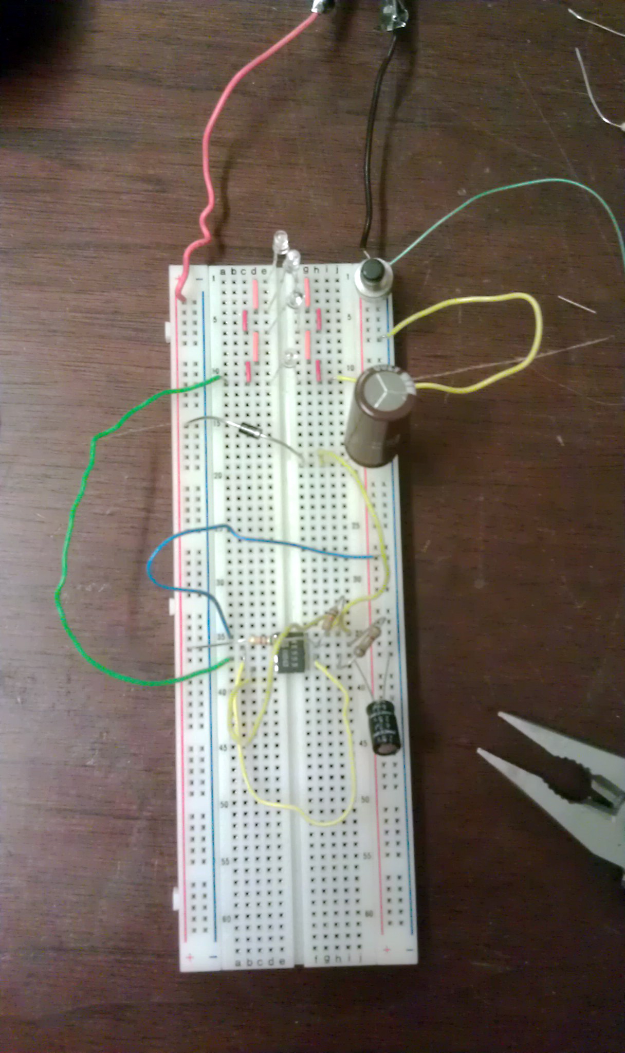
So, when I was in at the MILWAUKEE MAKERSPACE I asked Tom G if he had any suggestions for me to start learning electronics by building a simple PWM dimmer for my fish tank LED light. As a hobby, he has built a fair number of robots, and pointed me to the Dallas Personal Robotics Group web page, where they had a number of tutorials posted. Sure enough, they had atutorial on building a simple motor speed controller, using a 555 timer chip. It also included a very nice explanation of Pulse Width Modulation. It’s really a simple thing that is sometimes hard to describe. I don’t think I have ever heard it explained so clearly as in the DPRG tutorial.
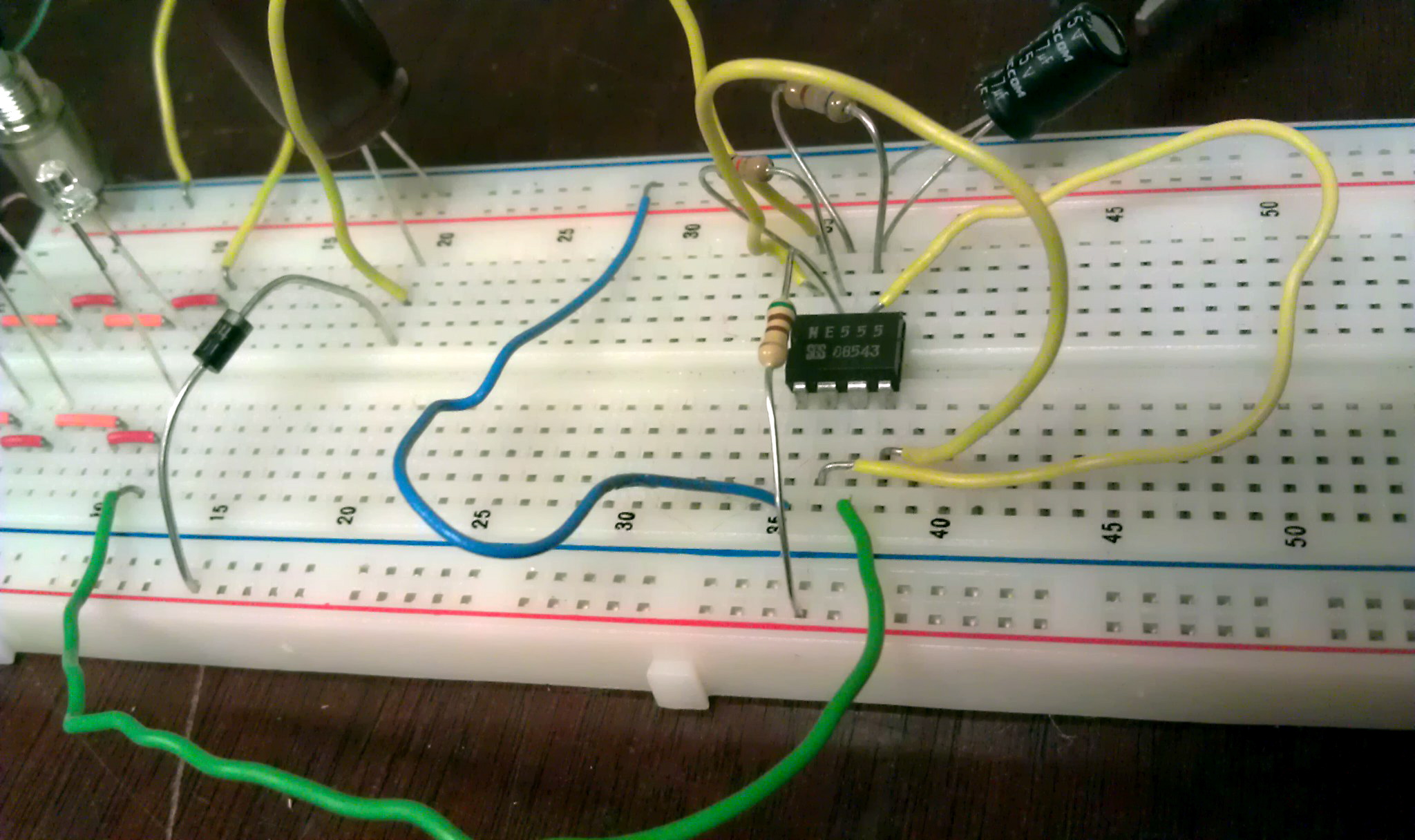
Part of the fun of the Milwaukee Makerspace is just having lots of odds and ends around handy, instead of having to take a trip out to the hardware store or electronics warehouse. A 555 timer, a few resistors and capacitors, and a bread-board were I all right there, ready for me to prototype this simple circuit. Even with nearly no electronics experience, it was pretty easy for me to follow the tutorial and connect up the 555 and other components into a working circuit.
After some playing around with it, I found that this circuit could not only control the speed of a DC motor, or dim an LED light, but somebody else suggested I hook a speaker up to it. Sure enough, I could generate various frequencies of sound as well! (Although since it’s a square-wave, none of them sounded very nice!)
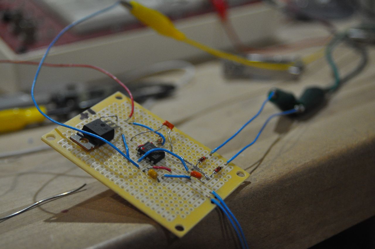
So, the next time I was going past Radio Shack, I stopped in and picked up some “Perf-Board”. It’s sort of the step between a breadboard and a custom circuit board – just a board with a bunch of holes in it, all evenly spaced, ready for you to insert electronic components and solder them together.
I then recreated my original breadboarded circuit on the perf-board and soldered it all together.
I also grabbed a used plastic case from the Makerspace parts pile to use as an enclosure for the circuit-board. A bit more scrounging meant that I had a power connector for it that matched the power supply for the LED light. I’d be able to use the same power supply whether I was using the LED with or without the dimmer.
A bit more soldering (only ONE soldering iron burn!) and installing the board in it’s case, and I now officially had a PWM Light Dimmer for my aquarium!
But here’s where it gets more interesting. I really built this not so much out of need for a dimmer, but as a learning experience to find out where theory and practice come crashing together in the real world. After assembly, I already noticed a few ways to improve the final version of the device. (I’m still thinking of this as a proto-type or first run!)
Ideas for future improvements include:
1) A power indicator light. If the PWM is turned all the way down, it’s hard to tell if the device plugged into the dimmer is even on or not.
2) A volt-meter display. It’s pretty neat to be able to see that the perceived output voltage of the dimmer is. I have several 12V devices that I would like to run from a large 14.4V battery. With a volt-meter built in, I could set the dimmer to send exactly the correct output.
3) Battery Operation. The surplus case that I used as an enclosure already has a removable cover. It shouldn’t be tough to fit some AA batteries in there to make the whole thing run without requiring a power cord to the wall.
Recently, we through a birthday party for a friend of ours. She requested a Disco Ball at the party. My sister found a disco ball at the clearance table at a store, but no matching disco ball motor.
Aha! Here’s my chance to not only save a few bucks by not PURCHASING one, but also learn about motors and gear reduction! Next time I was in at the Makerspace, I dug through the bin of scrap motors on the “Hack Rack”. An AC motor? No that’s no good, it has to run on batteries.. Stepper motor? I have no idea how to run one of those…. Hmmm. What’s this? I eventually found not one, but two motors, both connected to to some gearing and a pair of tiny square drive axles. The motors were marked as 24V DC, and I knew that if I drove them at a lower voltage, they would still work, but not spin as fast. I tested them both with a benchtop power supply and saw that they worked. The one was geared to a much faster speed than the other.
I later tried running both directly from a 9V battery, as it is the simplest power supply I could think of. The one motor, through the gear reduction, would spin the driveshaft at exactly 2 revolutions per minute at nine volts. That’s almost PERFECT disco ball rotation speed!
I bent a paper clip through a connector on the end of the drive shaft to hold the ball, and added a carbineer to hold the motor to the ceiling. POW – top-notch disco ball rotation!
For the party, I let it run on just the 9V battery. It got left on overnight, and was still running the next afternoon. What a nice, efficient motor!
But what if I wanted to spin that ball a bit faster or slower? Either motor was designed to run up to 24 volts. My PWM “dimmer” was really a motor controller anyways after all. That was all set up for 12V. I connected the dimmer to the more quickly geared motor, hung it up, and strung the disco ball from it. Sure enough, by varying the potentiometer on the dimmer, I could make the ball spin from way too slow to nausea-inducing quick!
I even noticed that at very slow speeds, the motor made a little bit of a high-pitched whine. Remember how I said an audio speaker could be hooked up to generate a tone? At slow speeds, the pulses of the motor controller can actually be heard – the frequency is within the range of human hearing. The first time I ever heard a Chevy Volt, I noticed that it made a quiet, yet distinct noise right as it accelerated away from a dead stop. That’s the sound of the car’s electric motor controller picking up frequency as the car increases speed.
So there you have it. From dimming a light, to spinning a ball, to driving an electric car, Pulse Width Modulation is a simple, yet useful, trick that’s all around us. If you would like to build your own basic light dimmer/motor controller, check out the info at: http://www.dprg.org/tutorials/2005-11a/index.html
But why stop there? Once you have some mad soldering skills, what’s to stop you from building a bigger version of a motor controller, maybe something that can push a full size car around? Check out the Open Revolt controller – a motor controller anyone is welcome to build! http://www.instructables.com/id/Homemade-100-HP-Motor-Controller-for-an-Electric-C/
If you are anything like me, you like to learn new things, and find it fascinating how various areas of industry and science are all related. It’s far more fun to build and design something yourself then it is to just purchase somebody else’s.