Electric Ice Scooter

DSC_0424

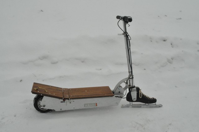
When I recently was at the thrift store and saw a pair of ice skates next to a kick-scooter, it got my mind going. “What would a scooter look like with skates in place of wheels!?”

The next time I was at the Makerspace, I saw my old electric scooter over on the Hack Rack. This was a scooter I originally rescued from a dumpster. Although it didn’t have batteries, just adding power and a little tinkering got it up and running again. A few of the EV Club and PowerWheels Racing guys played around with the scooter a bit, but eventually the controller got toasted, and who knows what happened to the front wheel.

Oh well, I’d be replacing that front wheel with an ice skate anyways.

Turns out that the heel of an ice skate is actually sturdy enough to drill right through and use as a mounting point. I simply  drilled through the skate, inserted a spacer, and then ran a 3/8″ bolt through the skate and the front fork of the scooter. I finished it off with a couple of washers and a nut.

Then next thing to fix was to get the  motor going again. Turns out that it’s a brushless motor. While I have a fair amount of experience now with BRUSHED motors, this was my first experience with brushless. I did a little research, and then ordered a 24V, 250 watt generic brushless controller from a mail-order scooter parts company. Unfortunately, it used a different style of throttle than what was already on the scooter, so I had to order a throttle to match.

Connecting the controller was pretty easy, three wires to the motor and the black and red one to power. I first bench-tested it with an old printer power supply, and once everything was working right, bit the bullet and bought a brand new pair of 12ah SLA batteries. The two batteries are wired in series, along with a 20 amp fuse, and then go to the controller.

I still needed a deck for the scooter. I dug through some scrap materials and found a pair of cabinet doors that were about the right size. I cut them down just a bit and bolted them to the scooter. I even re-mounted a cabinet door handle to have as an attachment point for towing a sled.

With that, I was ready to go for a test ride, so it was off to the lake. Once I was on the ice, I turned on the scooter and gave it a go! What fun! It really zipped along, but it was almost impossible to steer, as the back tire would slip right out from under me! Time for more traction!

I decided to make a spiked tire. I removed the rear wheel, then disassembled the two-part rim and removed the tire and inner tube. I stuck 1/2″ self-tapping, pan-head, sheet-metal screws through the tire from the inside, so that their points stuck out.DSC_0394 I evenly spaced out 24 screws and alternated them to be slightly off-center side to side. Next, I put some old scrap bicycle inner tube over them as a liner to protect the scooter tire inner-tube. After that, it was just a matter of reassembling everything.

Now for test #2 out  on the ice. Remembering how much it hurt to fall on the ice, I was prepared this time by wearing my motorcycle jacket (which has padding built-in) and my helmet. Good thing too, as I would learn while steering with one hand and holding a GoPro camera in the other…. (Note to self, keep both hands on handlebars at all times.)

Overall, the Ice Scooter works great! I still have a few little things to do on it. For example, the motor is running “sensor less”, and I’d like to learn about how brushless motors use the sensor system. I’d also like to get a small 24V dedicated charger. As it is right now, I have to remove the deck and manually charge with a little 12V charger.

From thrift store idea, to hack rack, to life on the ice, it’s always fun to see what you can do with just a little ingenuity. I hope you like this project. If you want to see more on it, please check out the write-up I did on Instructables. It’s even in a few contests there, and I’d love your vote!

Keep on Making,

-Ben

Laser Cutter Venting System, Version 5.0

Sometimes solving one problem creates a few new ones! As part of the Laser Cutter Room Reconfiguration, the exhaust system got an upgrade. A new, bigger, more powerful fan meant we needed a new way to control it. The previous system (Version 4.0) was a simple on/off switch. That just wasn’t going to cut it for this industrial grade blower. Tom G., Tony W., myself and others spent the holidays installing this new two-horsepower beast above the ceiling in the Craft Lab. Once it was hung from the roof joists with care, Tom got to work ducting it over to the Laser Cutter Room. Finally, when all the heavy lifting had been done and the motor drive had been wired up, all we needed was an enclosure for the switch.

The request went out on the message board. Pete P., Shane T., and I all expressed interest, but life got in the way and it soon became a matter of whomever got to it first would be the one to make it. I ended up devoting the better part of last weekend to this project (much more time than I anticipated) but I can honestly say I’m pretty happy with the result.

LCEC01

The goal was fairly straight-forward: make an enclosure for the switch Tom had already provided. It was a color-coded, 4-button, mechanical switch that had been wired to provide four settings: OFF, LOW, MEDIUM, and HIGH. The more laser cutters in use, the more air you’d need and the higher the setting you should choose. There’s four duct connections available for the three laser cutters we currently have.

There’s a saying: “Better is the enemy of done.” Truer words have never been spoken in a makerspace.

At first I wanted to build the enclosure out of acrylic. Then I remembered this awesome plastic bending technique that Tony W. and some others told me about. I found a video on the Tested website and got inspired. (If you don’t know about Tested, please go check it out. You’ll thank me later.) Unfortunately, my bends kept breaking and melting through, so after a few hours of tinkering I moved on.

Thankfully, we have a small cache of plastic and metal project enclosures on our our Hack Rack. I managed to find a clear plastic, vandal-proof thermostat guard. It looked workable.

I tried laser cutting it, but the moment I saw the plastic yellow and smoke, I knew there was probably some nasty, toxic stuff in it, so I moved to the CNC router. About an hour later I had my holes cut.

Then came the wiring. Up until this point I had been focused on the control box itself. Now I wanted to add a light!

No, two lights! Yeah!

One light to tell you when everything was off, and another that lit whenever the fan was in use. People could look at the lights from outside the room and instantly know if the fan had been left on. (It should be noted that the new fan, despite being twice as powerful than our last, is actually much quieter. Tom added a homemade muffler to the inlet of the blower and shrouded the whole contraption in 3″ fiberglass batt insulation. The best way to know if the fan is running is to open a slide gate damper and hear air being sucked in.)

OK, I totally got this.

Draw myself a ladder diagram and get out the wire connectors… Remember that I need to isolate the signals from each other so any button doesn’t call for 100% fan… A few more relays… Some testing… and done!

Wait a second… the motor drive doesn’t have a ground for the control signal.

Hmm.

Guess I can’t power it from the drive. I’ll just tie into the drive’s ground. Nope, that didn’t work.

I’ll read the motor drive manual. OK, it has a set of “run status” contacts I can monitor.
….and they’re putting out a steady 0.4 volts DC. That’s enough to light up a single LED! …except, no. It’s not lighting. Doesn’t seem to be any real current.

I’ll just use a transistor! That’s the whole point of a transistor!
….well nothing I tried worked.

I’ll build a voltage multiplier circuit!
….and this isn’t working either.

On Day 3 of this “little project” Ron B. made a comment about using a pressure switch of some kind.

Wait.

We have a Hack Rack full of junk and I know there’s this old bunch of gas furnace parts. It couldn’t be that easy…

LCEC02

Yeah. So, three days (and a few frustrating epiphanies) later, this all came together. Press the beige button, get some air. Press the other buttons, get some more air. Any time there’s suction, the red light comes on. The indicator light is powered by its own 24 volt DC wall pack. The pressure switch has both normally open (N.O.) and normally closed (N.C.) contacts so it would be totally feasible to add another light at some point. The controller could display “OFF” or “SAFE” or whatever as well as “ON” or “FAN IN USE” or whatever. The text is just a red piece of paper with words printed on it, then holes laser-cut out to fit. We can trade it out with different words or graphics if we ever feel the need. I was just glad to have it done, so I called it. Better is the enemy of done, indeed.

LCEC03

You can learn more about the evolution of our laser cutter venting system on our wiki!

Fun with Lasers!

Just about the only thing I don’t love about the Open ReVolt motor controller is the case.

As cool as an Open Source Motor Controller is, it’s just not shown off with a basic metal cover. In fact, I actually drilled through the original cover (and put clear packaging tape over the holes!) to see the power and troubleshooting LEDs through the lid.

Recently, the Milwaukee Makerspace got itself a laser cutter. It’s not all that powerful, but more than capable for cutting plastics. One of the Makers posted a blog entry about making a wood box on the laser. He used a program called BOXMAKER which helps you layout the size of your box, including overlapping cut edges to put the whole thing together.

This got me started on the idea of building a clear plastic case for my 500 amp Open ReVolt controller. But I had never even used the laser before. I sat down with the member who owns the laser, and he took me through the basics of importing files, exporting to the laser, and modifying power and speed settings. With that, I was able to start making a few test items on the laser. I figured that since I already had the Open ReVolt logo as a vector file, it couldn’t be easier to try out etching some plastic with it.

I used the laser to make a few small test pieces on various materials. The two logos turned out pretty well. They were both etched AND cut out with the laser. On the orange medallion, I mirrored the image, so it would be a design on the “back” of the piece. That keeps the upside nice and shiny and clean.

Plastics cut on the laser


After practicing a bit on the laser, I started wondering what else I could cut, mark, or etch with the laser. Last night, I forgot something at the Makerspace, so I had to return there this morning to retrieve it. And I am NOT a morning person, so I had my trusty travel coffee mug with me. It’s stainless steel with an anodized dark gun metal finish to it. “I bet that would laser engrave nice!” I though to myself. Sure enough, it only took a little tinkering to figure out how to keep the mug from rolling sideways inside the laser before I could engrave it.

Also, when I came in this morning, all the lights were off, except for one – Tom’s LED lit plexiglass desk drawer. I asked him for some advice last night about how to engrave and then edge-light in clear plastic. He plugged in his project to show me a sample, and had left it on. It was eerily awesome to see the Makerspace lab lit up by green LED power! It’s a good example of how I would like to engrave the top of the controller case and light it up.

Well, that’s it for now. Next, I’ll have to take careful measurements of the controller, lay out the box, find some material to work with, and figure out where and how big the cuts in the end plates will need to be for the bus bars.

Unexpected Detour

When I arrived at the space Sunday, I had planned to work on a circuit board design in DipTrace.  After I left, I had spent six hours rewiring a golf cart.  Allow me to explain…

It all started when I went to take the trash out.  I used the golf cart with the flatbed to ferry the cans out to the dumpster.  After emptying the cans, I rode back and decided to charge the cart’s batteries.  Tom and Rich had just returned from lunch and Tom suggested we swap out batteries instead.  While swapping them out, we decided to also rewire them.  While rewiring them, part of the cart broke.  There’s a small white plate under the driver’s seat.  It’s about 4″ x 6″, likely made of asbestos, and holds a series of copper contacts that a lever attached to the gas pedal slides over to select the speed of the cart.  And it broke in two when we tried to tighten fix a wire on it.

We had a few options: try to mend the old, brittle plate, replace it with something new, rewire the whole thing, or scrap everything out for a solid state motor controller.  Not wanting to adopt a new project or sacrifice a motor controller that could be better used elsewhere, I volunteered to try and fabricate a replacement for the broken part.

First I documented everything just the way it was.  I labeled wires, took photos, scribbled down notes, etc.  Next I went about removing the broken plate.  There was probably more rust than metal on those bolts.  Then I took a pair of digital calipers and a ruler and measured the locations and sizes of holes for each component.  I considered using the CNC router or drilling a plate by hand, but the laser cutter seemed to be a much faster and precise approach.  I drew up my replacement plate in CorelDraw and found a scrap of 1/4″ acrylic that matched the size and thickness of the old plate.  After some tinkering with the printer driver and a dozen passes with the laser, I had a copy of the original in plastic form.

The next few hours were spent migrating the old parts over to the new one and wiring it back in.  Right around 7:00 PM, I tied some batteries together and the thing leaped forward.  A few more tests and it should be as good as new.  Someone suggested that maybe the plate was asbestos to avoid heating issues so we’ll keep an eye on that too.

Rotary Encoder – built into motor for Electric Car

My electric Dodge neon uses an AC motor and an industrial motor controller.  I upgraded from m 1984 motor controller to one less than 25 years old (actually less than 5.)

The new controller does much more than the old one and has the ability to do some fancy tricks.  At the moment I am running it in “sense vector” mode.  The controller senses the position of the armature by monitoring the current in the field coils.  This works great…   as long as the motor is spinning.  From a stop it tends to get out of sync, but there is a cure!

The controller can use a quaderature encoder so the encoder can read the position of the armature at any speed.

To add an encoder to the motor I decided to try a chip amde by Austrial Microsystem AS5040.  This chip senses a magnet near the chip and calculates the position of the magnet and can generate multiple output:  PWM, binary via I2C, and quadurature!

I bought a few of the chips and built a surface mount board to hold the chip and a few LEDs to display the output.  The first two version had a few problems but the 3rd time was the charm.


Thanks to Royce for working out the process for surface mount PCBs.


The final version had to be small enough to fit in a depression in the end of the motor cap.  The sensor centered and the whole board insulated (clear enamel)  since this is a grease pocket

for the rear motor bearing.


The magnet is mounted to a bolt that is threaded into a tapped hole in the back end of the armature.  It took a while to the position right (it needs to be within a few millimeters of the sensor) hence the nuts and washers.


The cable is brought out of the motor through a small threaded hole (it was an alternate location for the grease fitting.)  The hole is filled with epoxy and the wires go to a DB9 connector.   I built a small test board that shows the quadurature signals (4 round LEDs) and the status outputs from the chip (the two rectangular LEDs)


The motor controller puts out 15V to power an encoder and wants A and B as well as inverted A and B signals.  The circuit includes some NPN transistors along with a voltage regulator and a few capacitors to tie it all together.  I put the schematic for both the sensor and test board on one schematic so I could make both boards at the same time.

I installed it in the car today, but still need to put a few more parts together to run it.


DOH!

It doesn’t work!

Ok, so the electronics work fine, it talks to the controller.

But it tops out at 256 pulses per revolution and the controller needs 1024.  It was a minor confusion between terminology.  The sensor detects 1024 positions, but to generate quaderature it uses 4 positions per pulse output.

Back to the drawing board.


I picked up a commercial shaft encoder on ebay for 50 that outputs 1024 PPR but it only works at 5V, so I’ll need a level shifter board and connector adapter.

Oh, yea, and I need to put the motor again, take out the old encoder, bring a shaft extension through the back grease pocket, add a grease seal and couple it to the encoder.