I installed the Y-axis screw drive in MegaMax using the old NEMA-23 stepper motor. A couple really good things came from this:
1) I can now adjust the bed leveling screws from the underside of the bed using thumbwheels instead of a screw driver. I know, I know, everyone else in the world has been able to do this from day 1…

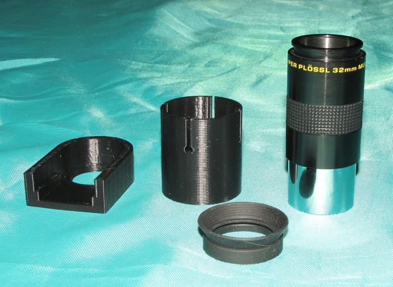
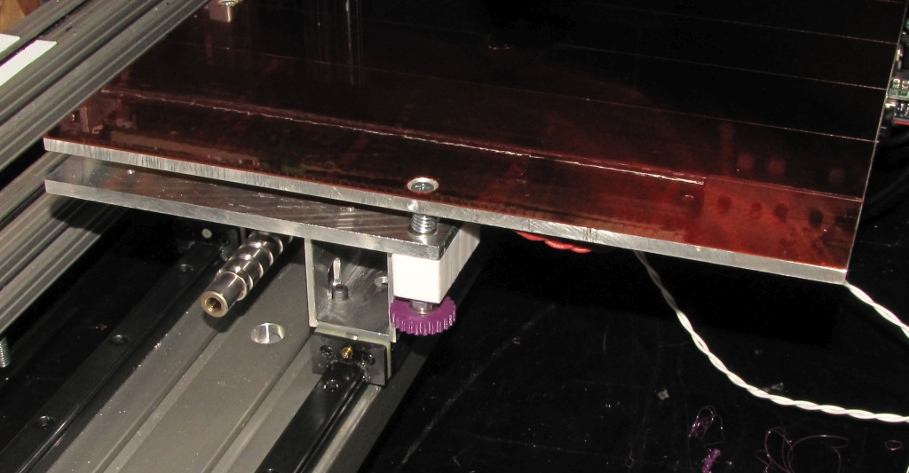
Thumb screw for leveling print bed. Screw is threaded into teflon block.
2) Unlike everyone else in the world, with fully supported linear guide rails, the print bed does not move in any direction but along the Y axis. In the old scheme, with the end-supported round guide rails, the rails would flex and the bed would move up and down when applying pressure to it (sometimes even the screw driver pressure to adjust the bed leveling screws). Now, if the bed moves at all in the vertical direction it’s because the bed plate (1/4″ aluminum) itself is flexing!
A couple bad things were also discovered:
1) The vibration and noise problem I was hoping to solve has not been solved. It has been made worse, though the character of the noise is improved to musical tones instead of just harsh buzzing and rattling.
2) Several failed test prints at ever decreasing jerk, acceleration, and speed settings have demonstrated that the old motor simply doesn’t have enough torque to drive the screw reliably at reasonable printing speeds.
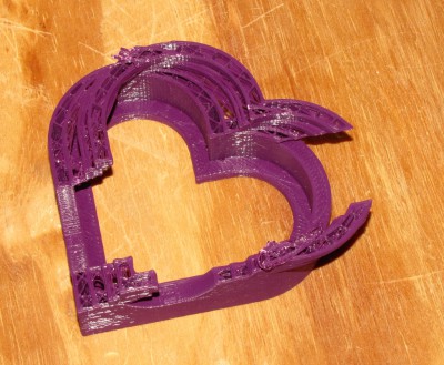
Shift occurred in Y-axis due to insufficient motor torque.
Further research into the first problem indicates that the vibration and noise are inherent in using steppers, and worse in MegaMax than in machines that use NEMA-17 motors because of the higher detent torque in the NEMA-23 size motors. Detent torque is the little bump-bump you feel when you turn the motor shaft by hand. The solution to the problem is to use a good driver for the motor and a higher voltage power supply. The little A4988 chips in the Pololu drivers on the RAMPS board are very unintelligent- all they do is provide microstepping. They work OK for NEMA-17 size motors because of the speeds and low detent torques in those motors. When used with NEMA-23 motors the driver limitations become apparent – as they have in MegaMax- lots of noise and vibration.
Good stepper drivers are DSP based and automatically sense resonance and damp it electronically. They use phase controlled sine wave currents to drive the motors smoothly. Fortunately, DSP stepper drivers for NEMA-23 size motors are pretty cheap. Here’s video of the DM542a driver pushing a NEMA-23 motor around. I have ordered a DM542a driver.
The best power supply for stepper drivers is not a switcher, and running steppers from a switching supply will often result in a dead power supply. I will be building a simple, unregulated transformer, rectifier, and filter cap supply to go with the new driver.
Next came the question of how to determine how much torque is needed to properly drive the Y-axis. A bit of research took me here: Motor size calculator. You just select the scheme for which you want to size the motor, enter the appropriate data, and it magically tells you how much torque you need to do the job. When I ran the numbers on MegaMax, it told me that I need about 350 oz-in of torque (about double the torque of the motor I have). I did a quick search and found a Chinese made (of course) 425 oz-in motor for $50. Also on order…
The motor mount I am using is designed for a NEMA-34 size motor with which I use an adapter plate to allow the NEMA-23 motor to fit. Since I’m buying a new motor anyway, why not just get a NEMA-34 motor? It turns out that the best stepper for the job is generally the smallest motor that can provide the necessary torque. A NEMA-34 motor could provide much more torque but the detent torque and rotor inertia would work against smooth and fast operation, and require a bigger power supply.
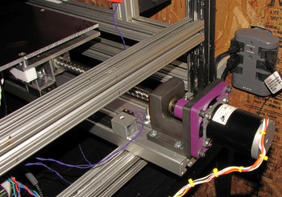
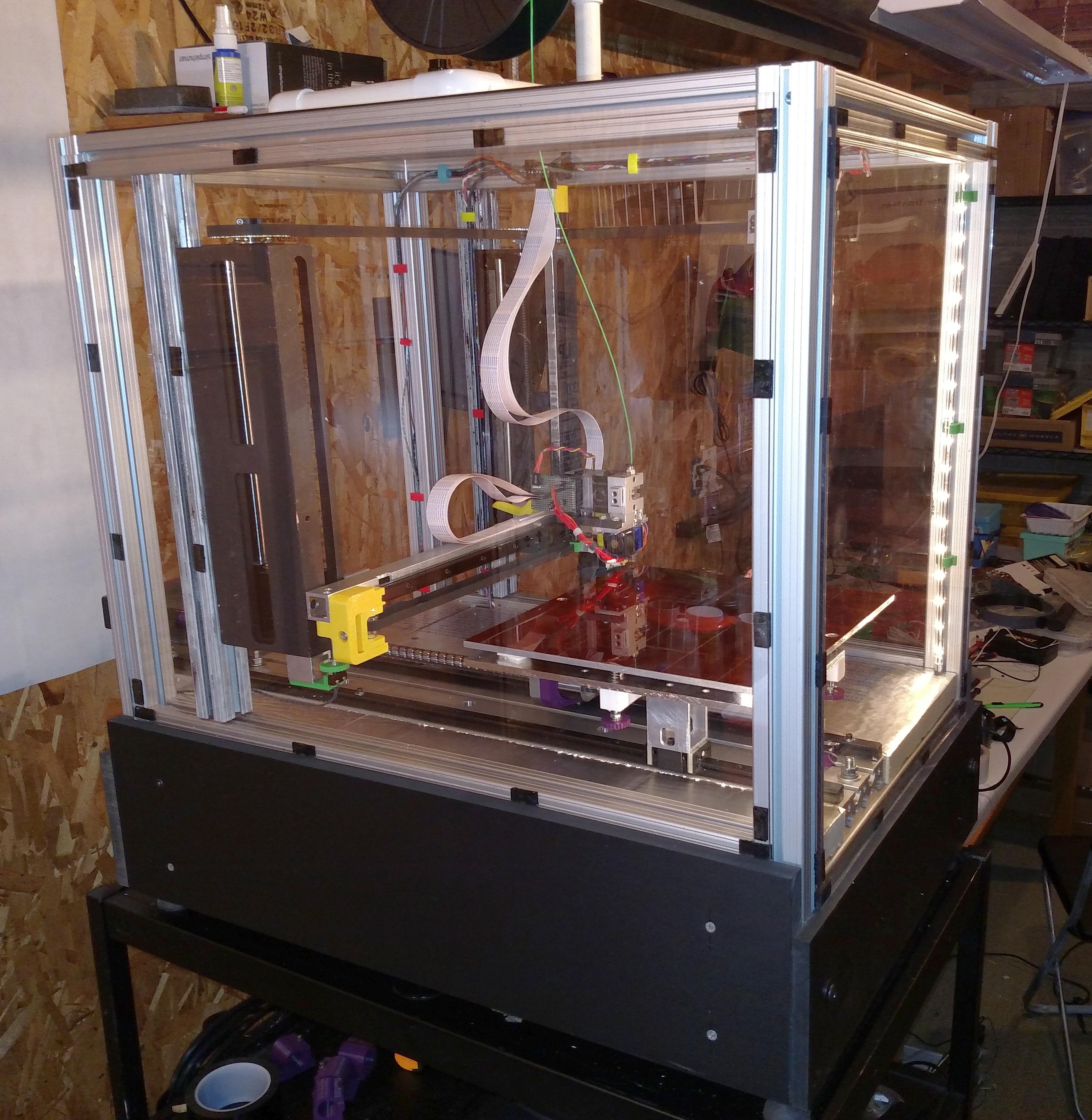
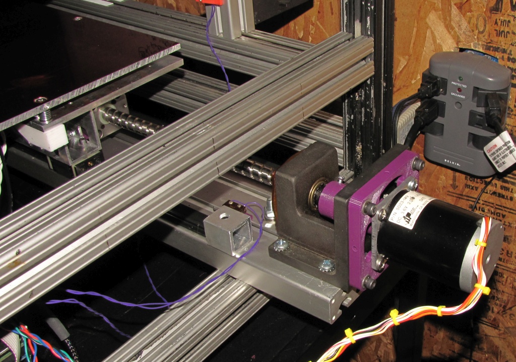
Back side of MegaMax showing motor mount, adapter plate, flexible coupler, and drive screw in Y-axis.
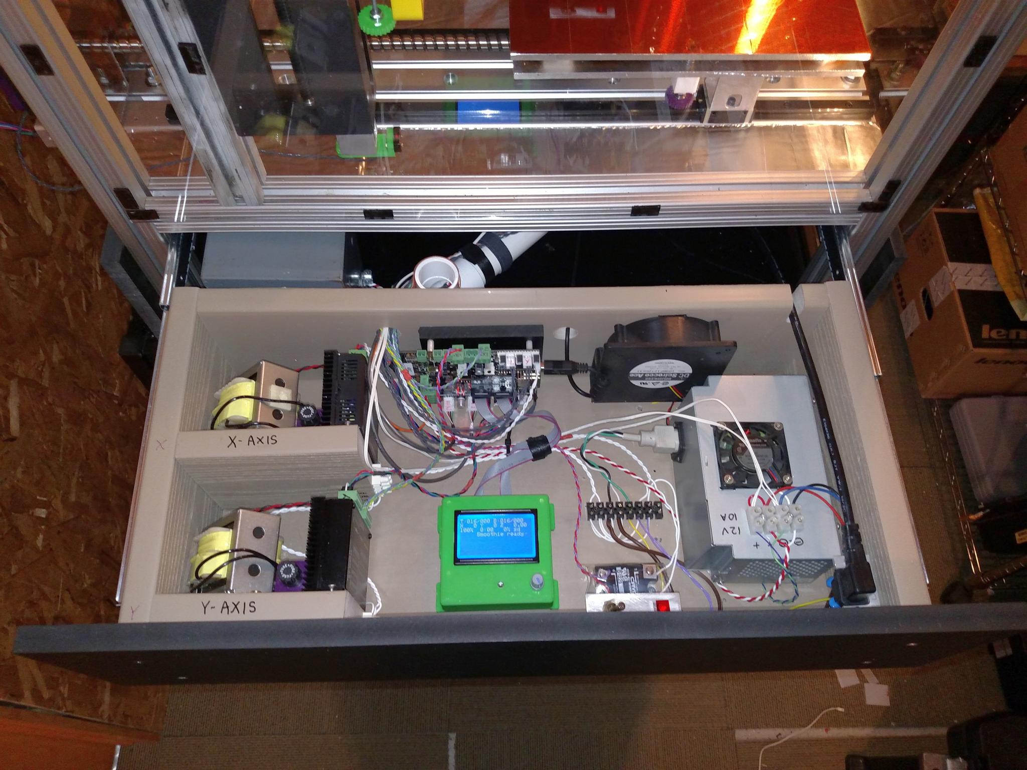
The ATmega2560 and RAMPS boards will be replaced by a SmoothieBoard. It has a much faster processor, much better connections for motors/external drivers, etc. It currently lacks an easy way to add an LCD controller, so I may have to connect to a computer to start prints up (it has ethernet and a built in web server so it can be accessed from any computer on the network). When a clean way to add an LCD controller becomes available, I’ll add it. SmoothieBoard review