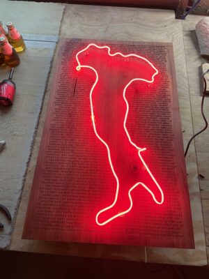
Background on this piece. This is the Italy “boot” in neon mounted to Walnut with engraved text. It is to commemorate a family vacation I took to Italy this year with the engraved text coming from sayings that we picked up from the trip.
Some detail on the process. The bending of the glass tube took roughly 15 hours over the course of a week. The Walnut was purchased rough, planed and jointed at the makerspace to get the boards square, and glued up into a panel. The panel was then cut down to size and run through the drum sander to even out any imperfections from the glue up. The engraved text was designed using inkscape and imported into CorelDraw for printing on “Katy Perry”, the 30W laser cutter. This panel was at the max cutting area for Katy Perry at 32″ x 18″. The cut took nearly 6 hours to complete. A box was constructed for the back of the panel to be used for concealing the electronics as well as a mounting point for the French cleat.
Total time to complete this piece was roughly 50 hours over the span of 2 weeks. Total material cost including glass, transformer, wood, stain, filling the tube with neon gas, and time on the laser cutter was roughly $200.
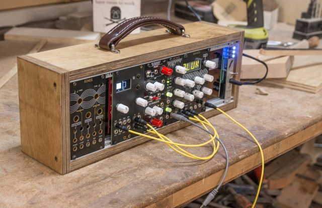
I’m building a modular synthesizer. Modular synthesizers are comprised of many discrete “modules” that generate, shape, or otherwise modify analog signals. These signals might be within the audible frequency range, meaning if you hook an amplifier or headphones into them you will hear sound, or they can be above or below the audible range and work as “control signals” which can interface with other modules to change how they shape the signals passing through them. There are a lot of signals, and there is a lot to learn about audio synthesis. There are a lot of youtube videos to explore the basics of modular synthesizers if you want to learn more.
This isn’t a blog post about modular synthesizers. This is a blog post about a wooden box. The wooden box pictured above is one of the first projects I’ve worked on at the Makerspace, and it’s the first wood project I’ve worked on since making a wooden trinket in shop class in high school. If I actually used a table saw back then (or any power tools), I have no recollection of it. I’ve always been more adept with a keyboard, mouse, or soldering iron than power tools, but I have been trying to expand my horizons over the years. Still, this was a more ambitious project for me than soldering together the electronic modules contained within. Continue reading →
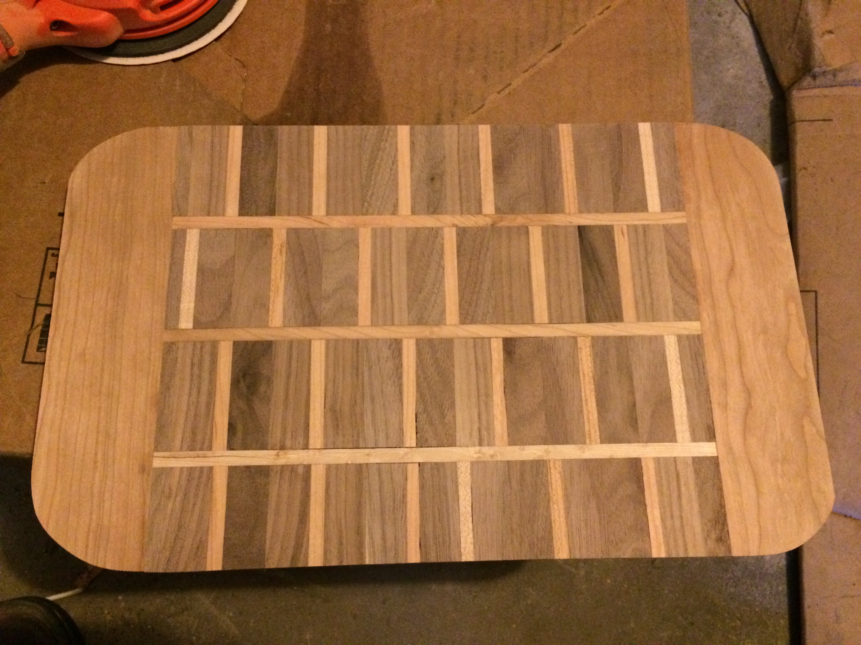
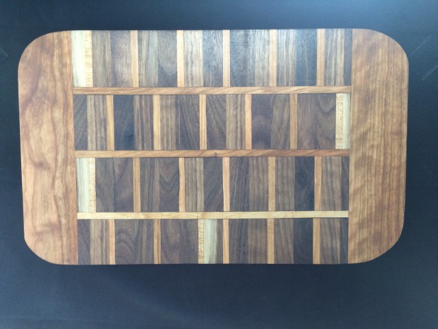
What started as an attempt to make a brick pattern cutting board, ended up as a “random” pattern with curly cherry ends. The side grain board consists of walnut, cherry, and maple.
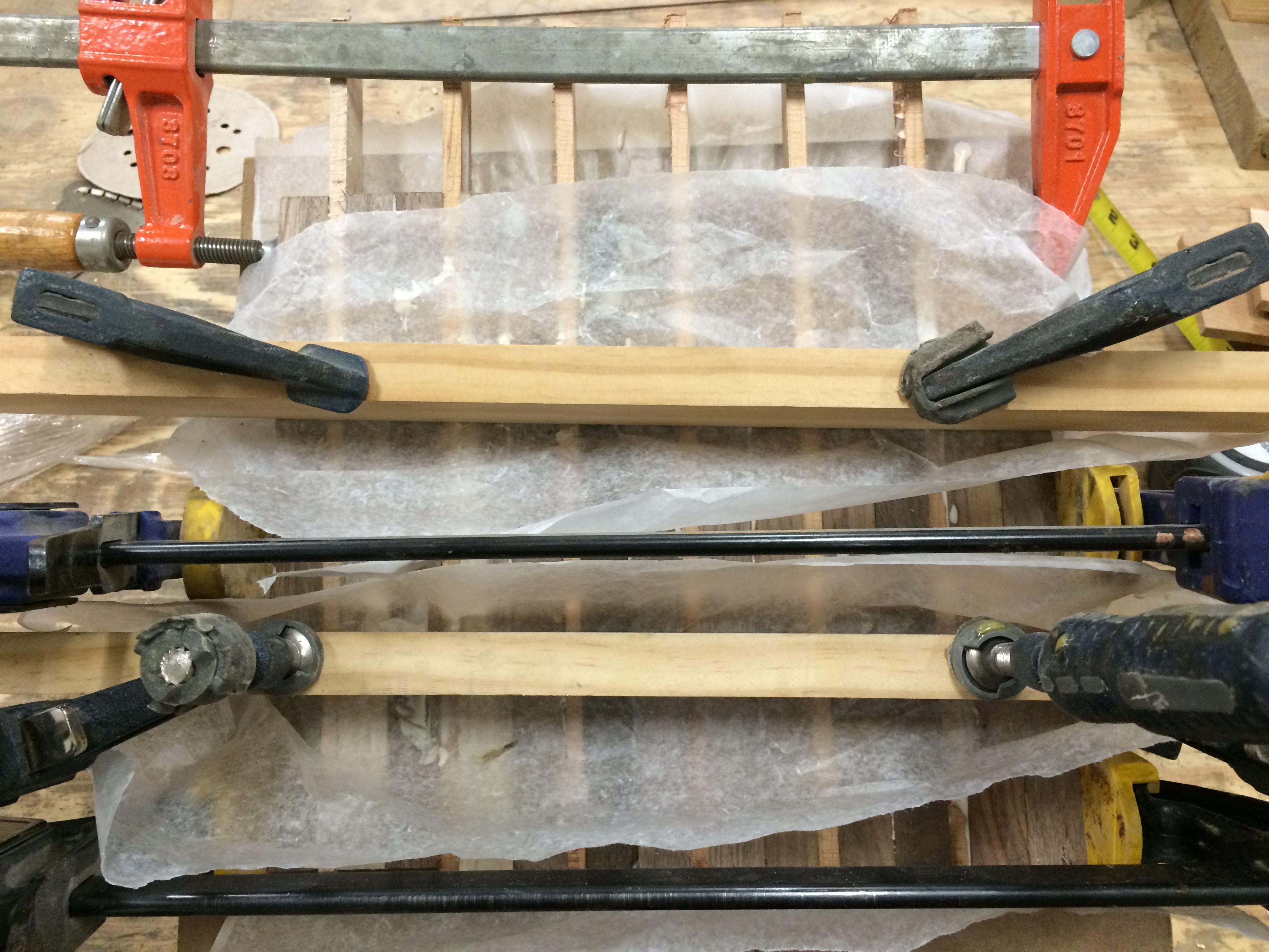
The process started by gluing a sandwich of (2) pieces of roughly 3/4″ walnut for every 1/4″ of maple of cherry or maple. One of the ends only received only one piece of walnut.
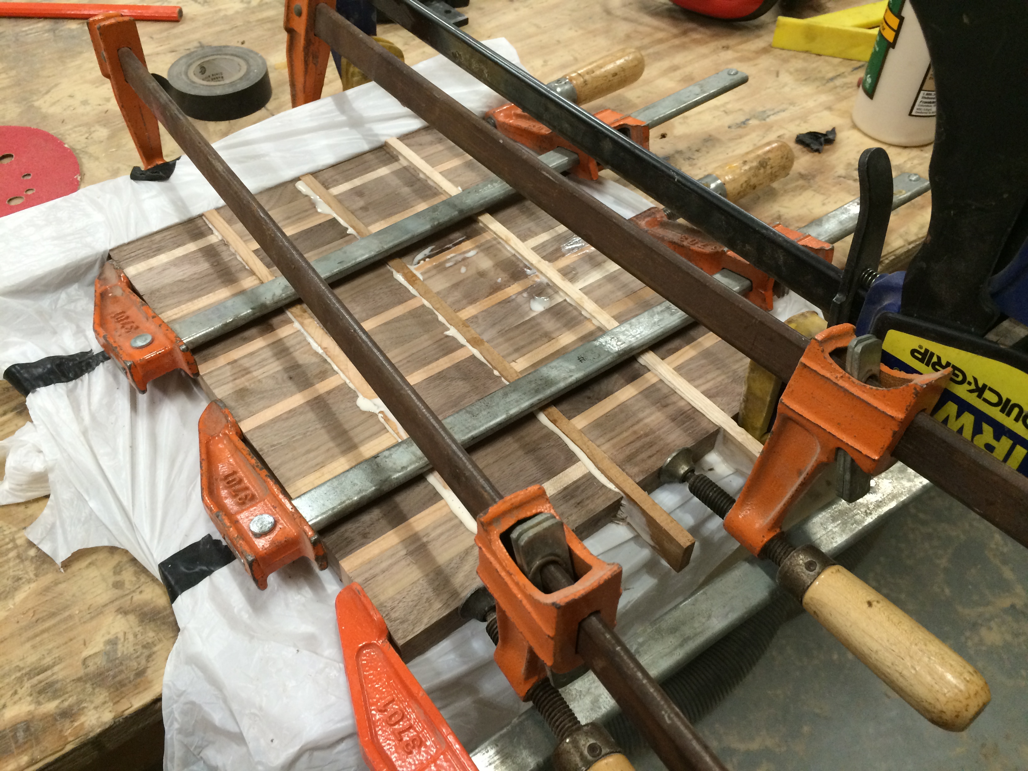
The assembly was un-clamped and ripped into (4) pieces using the table saw. They pieces were glued together again with another piece of cherry or maple in the middle. The side with (1) walnut was flipped in each column to create an brick and mortar like offset pattern.
I added curly cherry ends to increase the size of the board. These ends are face grain instead of side but since they won’t be seeing the knife much, it shouldn’t be an issue. A healthy dose of drum and random orbital sander was subsequently applied.
The board was soaked in mineral oil for (6) hours and finished with a beeswax and mineral oil mix.
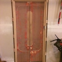
So, the STAR TREK DOOR has been a slow, “back-burner” project for a while. Recently, I got a little time, so I sat down and figured out how to hook up the air valves to a set of relays, and control those relays with an Arduino.
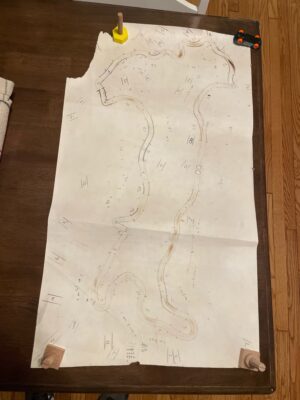
Here’s a video overview of the physical doors themselves and how we plan to open and close them with air valves.
This is a joint project, working on this with my brother-in-law, Fred. The doors are between his garage and workshop. Fred has been working on the doors themselves, the wall and framing, and mechanical connections. I’ve been working on figuring out the software, controls, and electronic magic that will drive everything.
The physical doors themselves are done, except for paint. Fred has also been making a pretty neat frame for the garage side. He cut alternating widths of wood and then glued them together for the nice light-colored wood on the inset of the planks that will frame out either side of the door. A similar piece will cross the top of the door.
I got all the main components – Arduino, breadboard, relay board, 12V power fuse panel, and air valves themselves all screwed to a piece of plywood. At this point, it’s not pretty, but it is functional.
We have a nice industrial door control with OPEN/CLOSE/STOP buttons on it. Those are momentary on buttons, but through the power of the Arduino, I can make them be whatever I want. I started with a Button Tutorial, and then modified it to suit my purposes, and added a Delay(1500) command after activating the air valve. That way, the valve will stay open long enough to fully open or close the door, even if the button is just pressed for a moment.
I programmed the pin for the STOP button to test out a sequence to open the door, pause (long enough for a person to walk though,) and then close the door. It seemed to work pretty well. If the timing is wrong for the real-world application, all I have to do is simply change the delay times. (It will also need a safety. We don’t want the door closing on a person!)
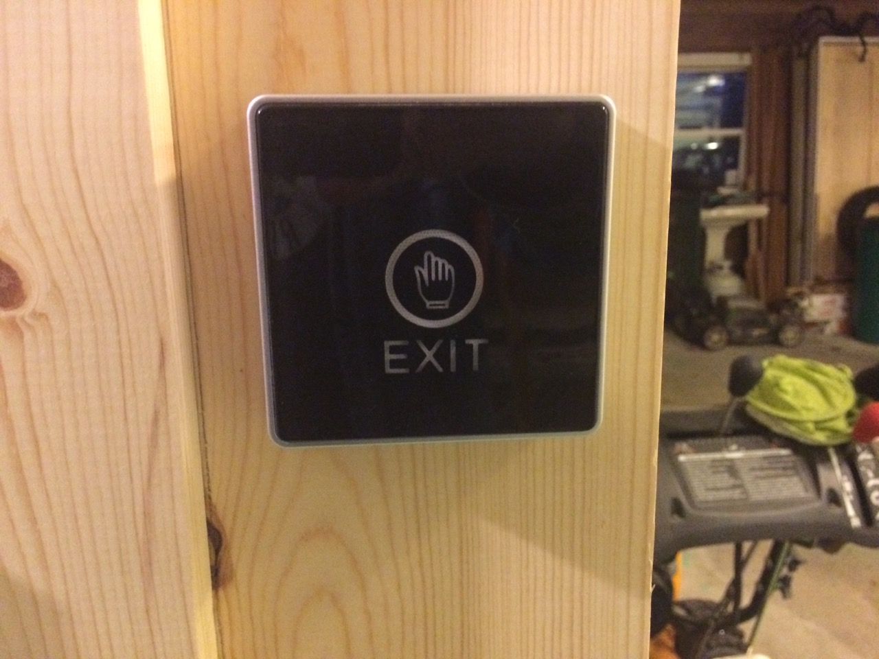
At this point, the basics of the control panel are working. The STOP button is just wired up as a “stand-in” for a single button we already have installed on the garage side of the door. It’s a capacitive touch button that lights up either blue or white with internal LEDs. It’s a neat looking button, but it’s only a SINGLE button. So, it needs to have functionality to both open AND close the door. I’d also like to explore using a variable in the Arduino that states whether or not the door is open, and then changes the functionality of that button based on whether the door is open or not. The air cylinders themselves also have built-in position sensors, which would be neat to use possibly as both a safety AND a “Is the door open or not?” sensor.
Here’s a video clip showing all the components actually working together. At this point, if the panel was simply mounted above the door, and air connected between the compressor and air cylinders, we would actually have functioning doors.
I don’t like the look of how the air valves and tees are held together right now. I was able to find some not-too-expensive push connectors (similar to PEX Sharkbite style) for air, which might make it a little easier to connect all the air components and look cleaner. Once I really have everything finalized on what’s going on at the breadboard, I also need to decide if I want to pull the breadboard out and replace it with a custom circuit board. One thing I DO need is a simple way to connect the tiny pin connectors to the larger wires going to the buttons AND provide strain relief. For the moment, I just used staples to nail the 18 ga lamp cord wire to the plywood and then made the electric connection with alligator clips. What would be the BEST/CLEANEST way to do this? Some sort of small screw down terminals?
I also have a rather large fuse panel mounted on the plywood. It was free, and I already had it. It supports many separate circuits, but for this project, a single DC fuse would probably be fine. I’m also using a bit of an overkill 12V power supply. I’ll want to replace that with a simple wall-wart. Lastly, the Arduino is running from USB power. I’ll need to solder up a 12V DC barrel connector so that it can run off the same power as everything else. I think we will make a switched electric outlet, and plug the wall-wart in to that. If the system is ever not working right, just switch off the power and manually open and close the door as needed.
I’ll definitely want to hang out with the guys at the Makerspace sometime soon talking Arduino, specifically how to integrate some more sensors and get feedback used to activate the doors fully automatically.
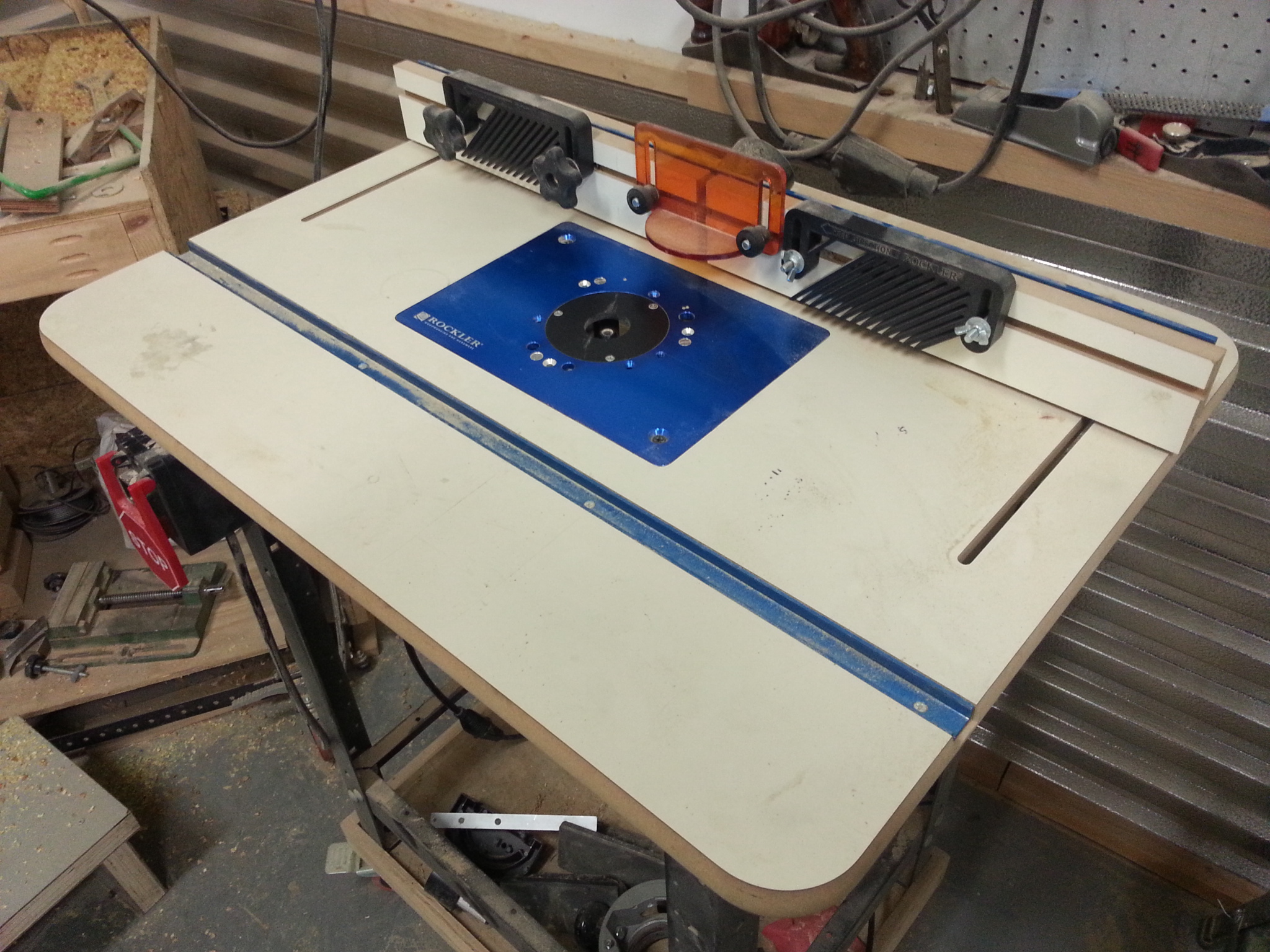
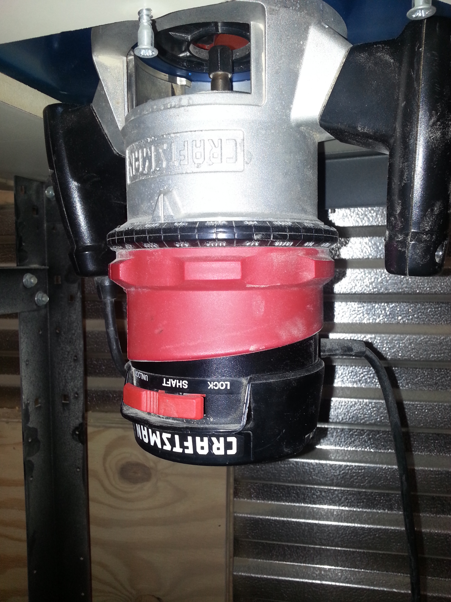
The woodshop now has a Rockler router table! Thanks to Bill M for donating the table and James for adapting the plate to an existing Craftsman router we can now use this fantastic router table. The table has a convenient switch(visible in the picture with a large safety STOP button), an adjustable fence, anti-kickback finger, slots for jigs, and is conveniently placed on wheels so the whole unit can be wheeled to where ever it is needed. If your wondering “what the heck is a router table, or a router for that matter” then check out the links below to get started.
Some great information on using a router table from Rockler is available here:
 I’m building a modular synthesizer. Modular synthesizers are comprised of many discrete “modules” that generate, shape, or otherwise modify analog signals. These signals might be within the audible frequency range, meaning if you hook an amplifier or headphones into them you will hear sound, or they can be above or below the audible range and work as “control signals” which can interface with other modules to change how they shape the signals passing through them. There are a lot of signals, and there is a lot to learn about audio synthesis. There are a lot of
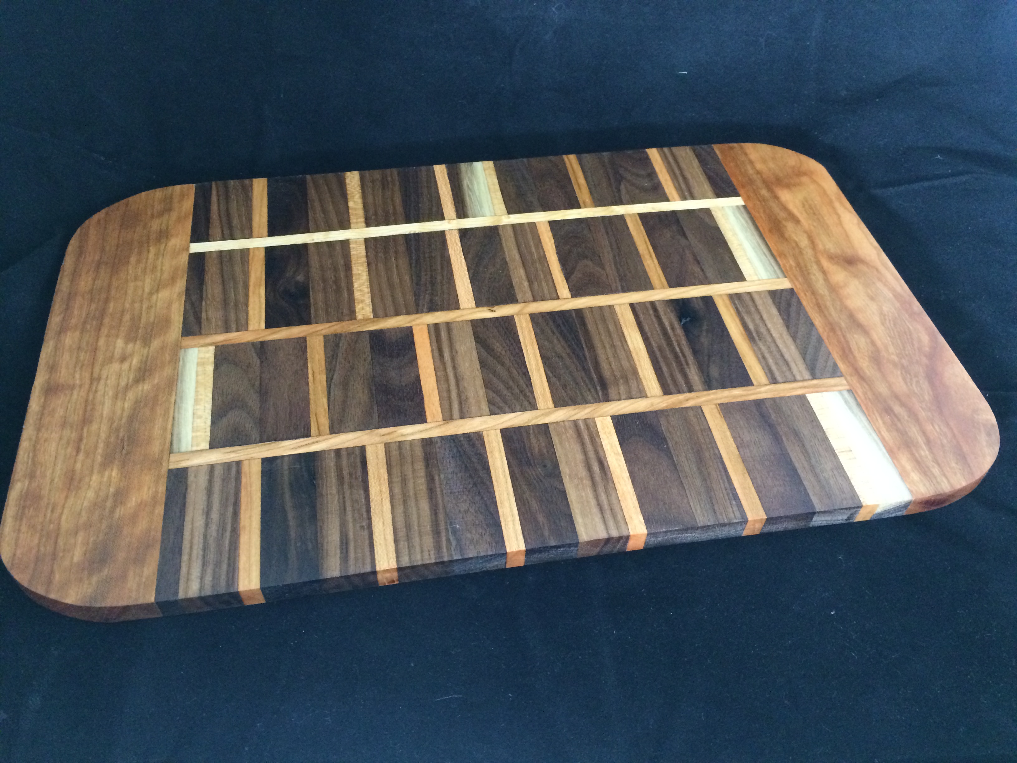
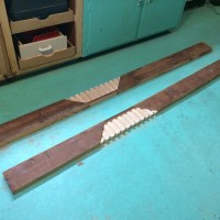 The physical doors themselves are done, except for paint. Fred has also been making a pretty neat frame for the garage side. He cut alternating widths of wood and then glued them together for the nice light-colored wood on the inset of the planks that will frame out either side of the door. A similar piece will cross the top of the door.
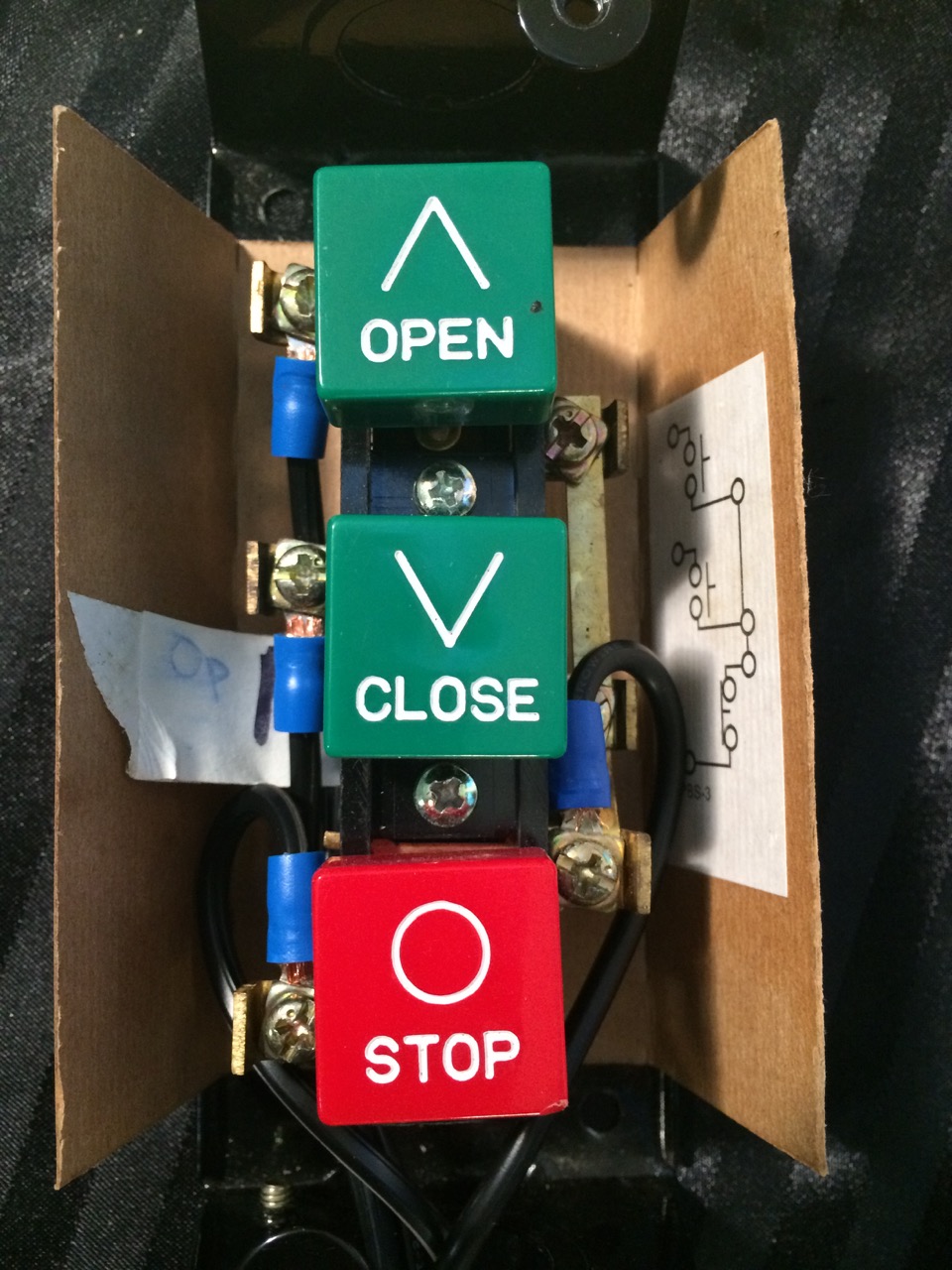

