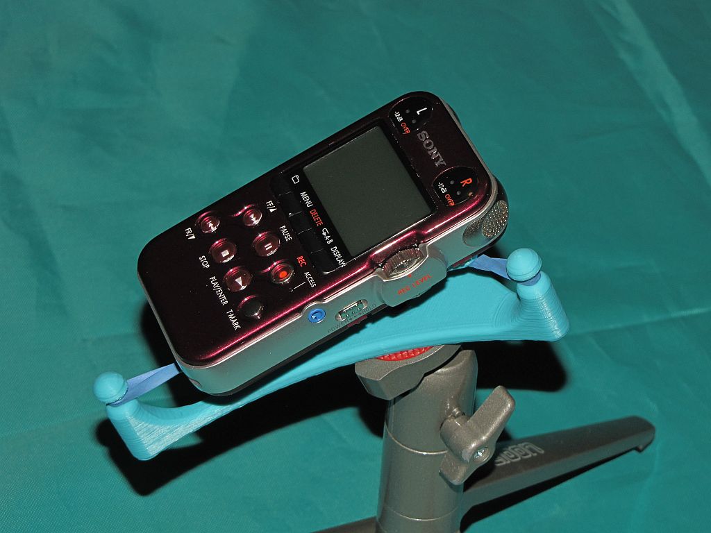
PCM-M10 Shock Mount
Several years ago I played with a lot of audio stuff including making binaural recordings of things like cicadas, train rides, and festivals in Japan, and the singing of tree frogs in my back yard when I lived in a forest in Missouri. Those recordings were done on a MiniDisc recorder because it was the best available audio quality recorder for people on a budget (i.e. cheapskates) like me. Time and technology wait for no one, and I’ve been getting the itch to do some recording again, so I recently picked up a Sony PCM-M10 recorder. This little machine records in many different formats up to and including 24 bit/96 ksps (though self-noise really limits the machine to about 15 actual bits). The audio is recorded onto micro SD cards so unlike the MiniDisc, you get access to the raw digital data without any compression or associated quality degradation.
My previous recordings were done using a DIY binaural microphone that used a roughly matched pair of electret condenser mic capsules mounted on a wire bail that held the capsules inside my ears. Even though those mic capsules were pretty noisy, the recordings came out pretty good. When you listen to them with headphones you get a real “you-are-there”, surround-sound experience that can be quite startling. You can hear those recordings here: http://mark.rehorst.com/Binaural_Recordings/index.html Soon, I’ll be starting a new binaural mic project to go with the new recorder, this time using much higher quality mic capsules.
In the meantime I was looking for a shock mount to use when making recordings using the built in mics. The shock mount prevents low frequency noise from handling, bumping the table the recorder sits on, etc., from being coupled to the mics through the body of the recorder. I did a web search and found only a couple unsatisfactory designs so I did what any maker would do- I made!
One of the flaws in the few designs I saw was that some of the numerous switches and I/O jacks on the recorder would not be accessible when it was bolted to the shock mount. They also didn’t look very nice. After a lot of sketching possible designs on a whiteboard and paring the thing down to a minimal implementation, and spending much too much time making a 3D model of the recorder, I came up with a printable 3-finger design that holds the recorder either on a tabletop or a tripod and keeps ALL the switches and I/Os available. The only thing you can’t do while the recorder is mounted is swap batteries (but with 40 hours record time on a set of two AAs, that shouldn’t be a problem).
I used DesignSpark Mechanical to make the recorder model and design the shock mount. DesignSpark makes rounding corners of complex 3D objects easy (nearly impossible in Sketchup), but I did run into some of its limitations that I hadn’t previously considered. One huge limitation is that there is no way to put any form of text into a drawing without some special work-arounds (use Sketchup to make text, then import into DesignSpark).
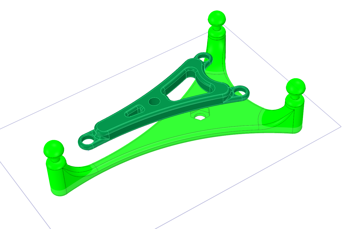
CAD drawing of shock mount
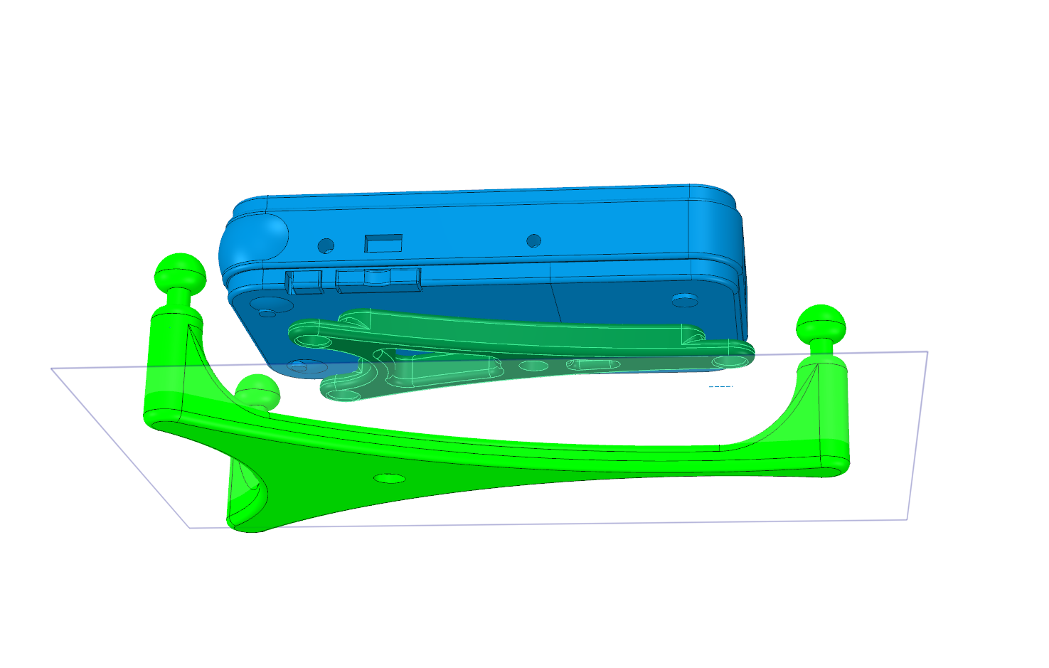
PCM-M10 on shock mount- CAD
This shock mount design is available here: http://www.thingi
I printed the shock mount on MegaMax using Coex3D Aqua ABS filament.