I added a trigger and it works beautifully!
You can DL the files here: http://www.thingiverse.com/thing:454265 and get your pew-pew on!
Be a part of a hacker/builder community where ideas are shared, innovation is fostered and the maker experience is hands-on.
Join us Tour the SpaceI added a trigger and it works beautifully!
You can DL the files here: http://www.thingiverse.com/thing:454265 and get your pew-pew on!
My recent acquisition of a Meade ETX-90 telescope with computer go-to system for locating objects in the sky got me thinking that it would be nice to have a system to locate objects in the sky when you’re looking through binoculars or a telescope that doesn’t have a computer and motors to drive it. To that end I came up with the idea of mounting a green laser pointer, commonly used by astronomy nutz to point out objects in the sky to noobs, on a cell phone or tablet running a program such as Google SkyMap or Skeye.
CAD rendering of the parts
After much thought and a few prototypes I came up with a system that allows a laser to mount on a phone and that assembly to mount on a tripod, a handle, or a telescope. The tube that holds the laser has adjustment screws to allow the laser to be aligned with the SkyMap on the phone. It also has to slots that fit over standard gun sight rails. On one side I have a phone/tablet bracket that has a gunsight rail and slides into the laser tube, and the other side can be used for a rail that mounts on a tripod or a handle. Extra rails can be mounted on telescope tubes. I haven’t yet designed a binocular mount, but will soon.
Parts printing on MegaMax
I printed the parts on MegaMax with Octave fluorescent red filament (that’s why the colors vary in the photos- the flash apparently excites the fluorescence in the picture with the handle). All the parts fit VERY tightly together but I included screw holes for extra security. The phone/tablet mounts on the bracket using velcro tape. I think it may be better to print or buy a cheap case to fit the phone than screw it to the phone/tablet bracket. I’ll be posting the design files to Thingiverse shortly.
Phone and laser mounted on handle
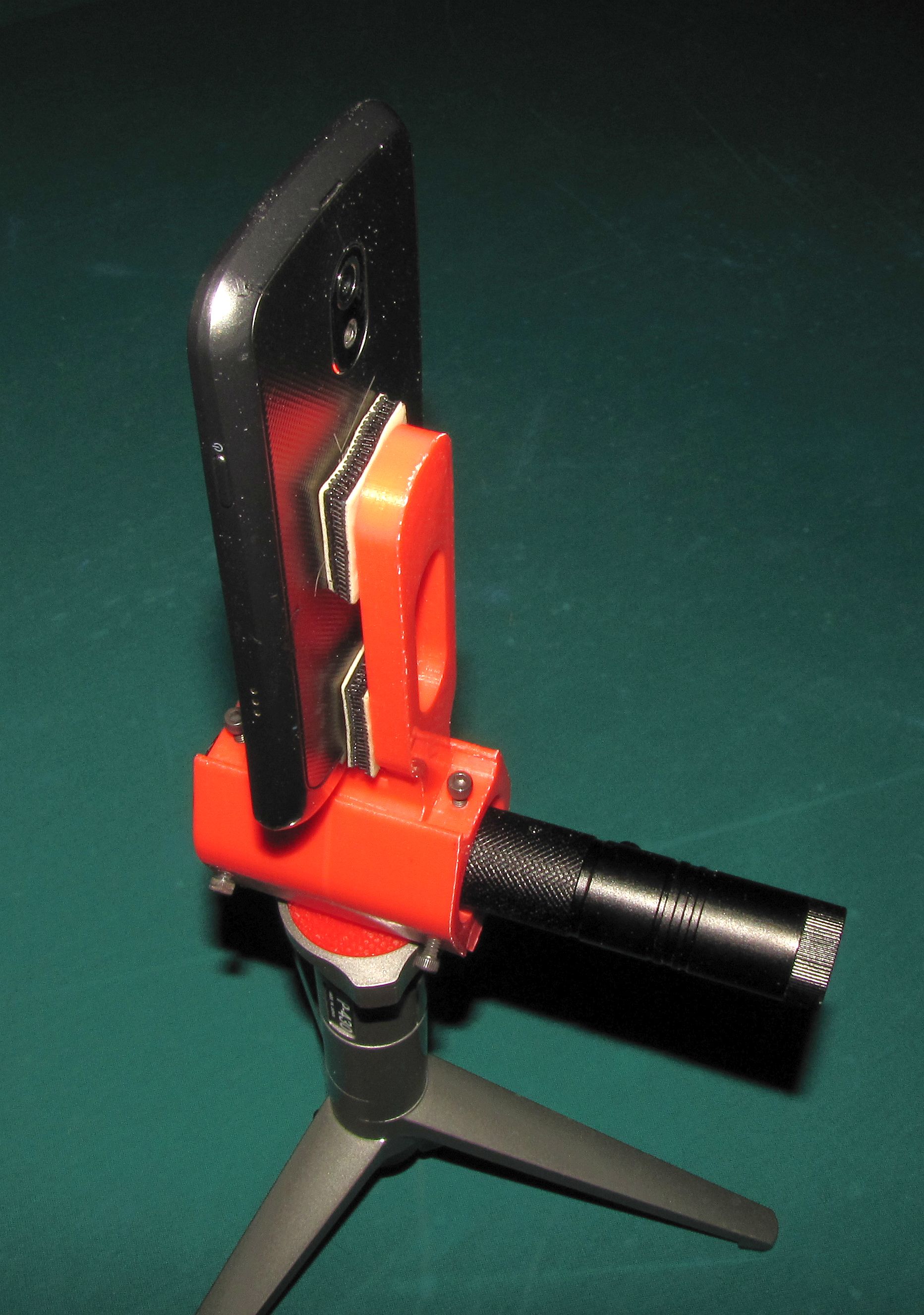
Phone and laser on a tripod
Occasionally back in the day, I would breakout the linoleum blocks and the speedball cutting tools, and carve out a design to make block prints. My experience in making prints spans from potato carvings to cardboard stencils, linoleum and wood blocks. As designs became larger, complex, and multi-color, the time it would take to carve the block plates, made finishing a project difficult at best.
Then, the laser cutter…..
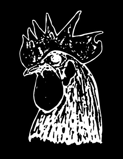
Using the adobe suite of products I created two black and white drawings to be translated to wood blocks.

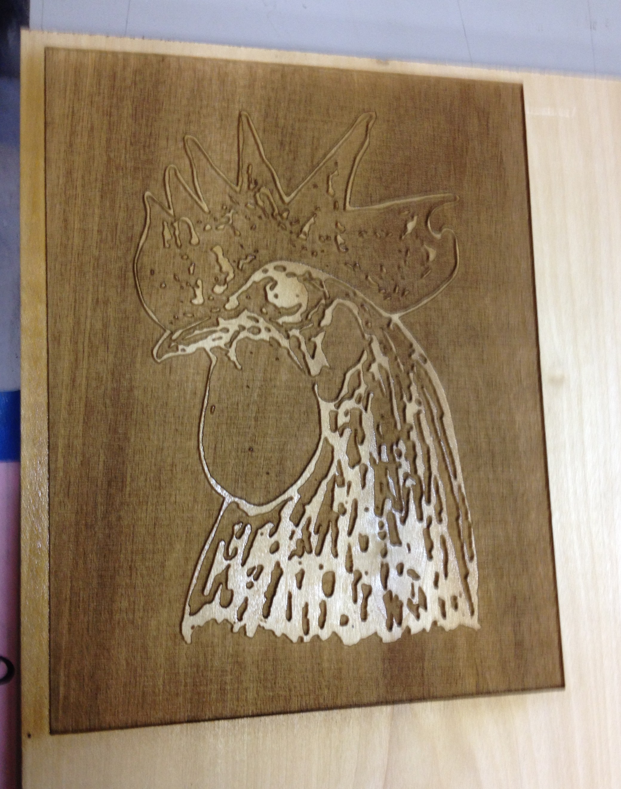
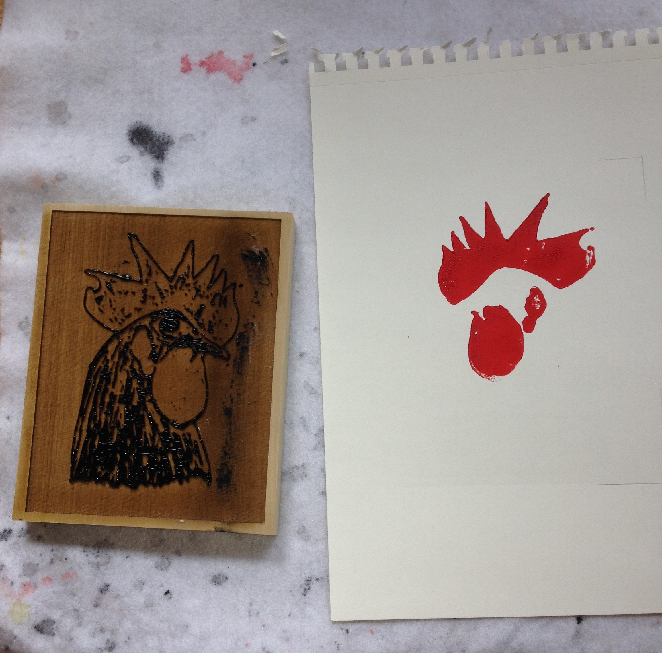
Unlike traditional transfer/carving methods, I decided to utilize the 60W laser to etch the images into poplar wood vs. carving. I chose poplar for its hardness and ability not to warp as easy as pine or other softer woods. 60W laser setting was 100 power, 60%speed, 500 PPI
The image below is a 5″x7″ laser cut of the black plate of the rooster image.
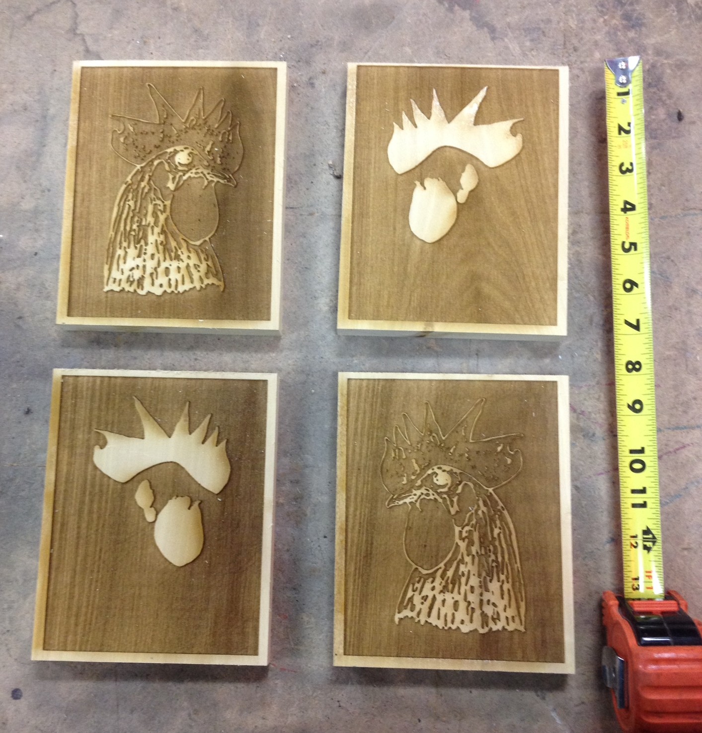
Top-Left is the black plate for the left facing rooster. Bottom-left is the red plate for the left facing, top-right – red plate, bottom right – black plate
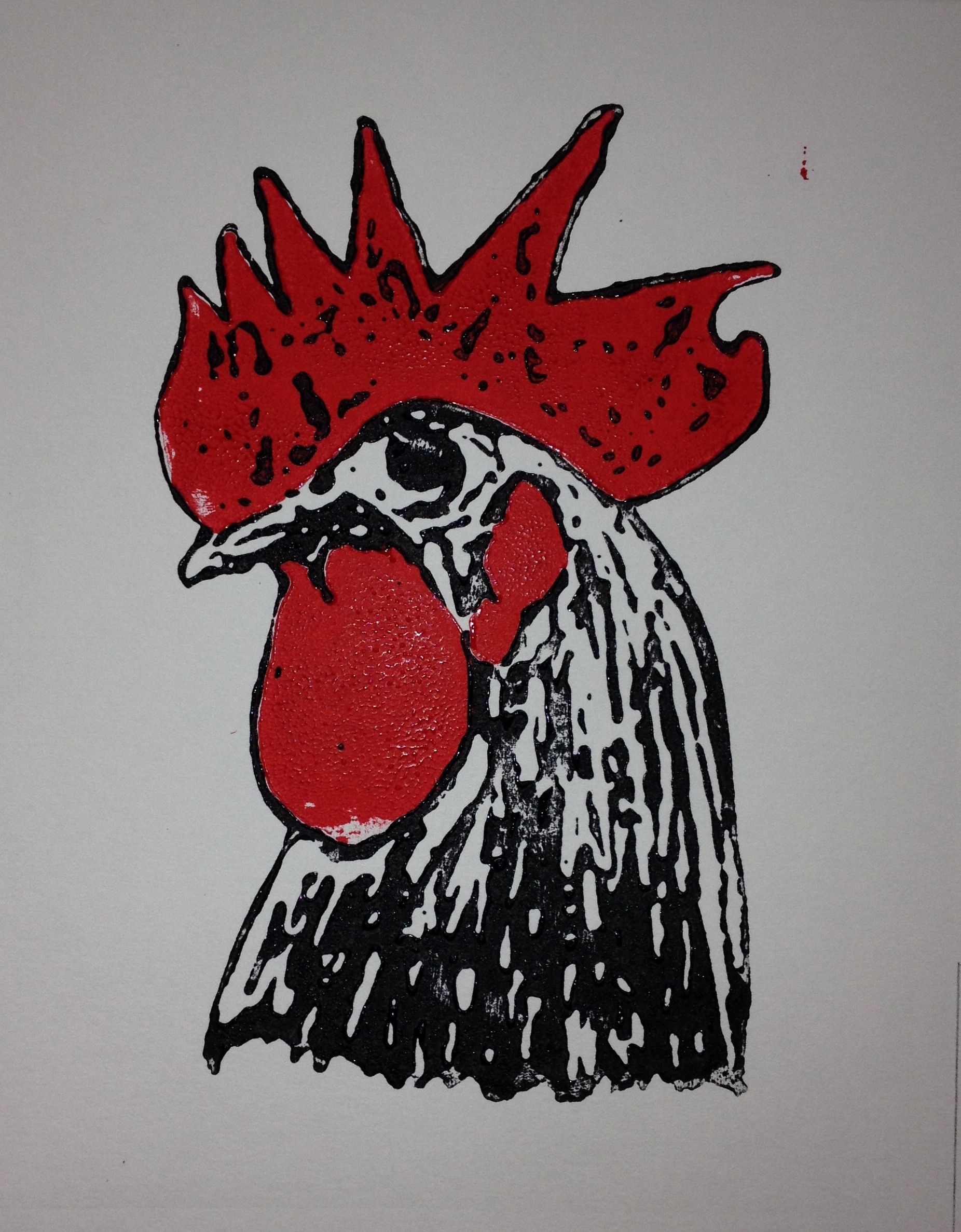
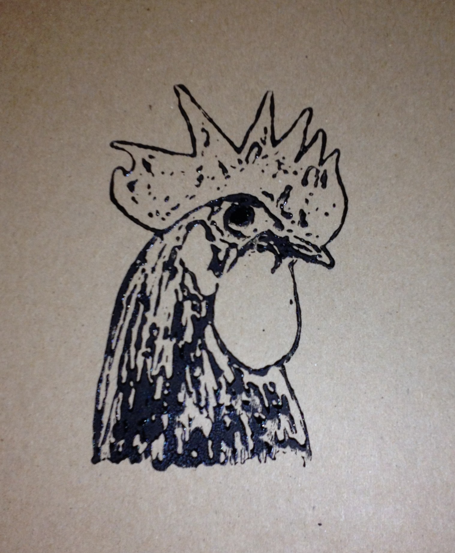
The following image shows the red left-facing plate printed, and the black plate inked up and ready to be printed
The first red/black rooster print, along side the right facing black print.
And of course, if you do one, you have to do many.

Simple. Add lasers.
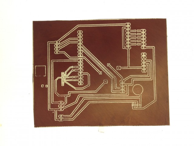
Video of Vectorized Laser PCB Fabrication
The next generation BADASS board was too big to fit through the card laminator, so I figured I’d try my hand at Tom’s laser etching method. By using the trace program included with CorelDraw I was able to make a vectorized path for the board. One pass takes about 5 min at 50% speed.
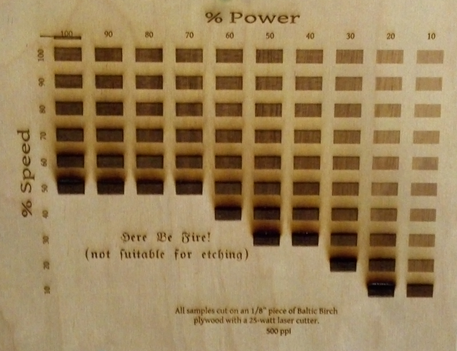
So, I was just getting in to the ‘Space when Jason G. and I started talking about the laser cutter. I had planned on doing some simple tests to determine the level of shading that I could get for an as-yet unnamed project when he mentioned that he (and others) were talking about doing a full map of different settings and the results.
I thought that I might as well give it a shot. The set up was interesting. I created a grid of rectangles in CorelDraw (oh, how I hate you!) and then used the preferences dialogue in the laser cutter driver to adjust the speed and power for each little square.
I should explain that the driver recognizes 8 colors and for each color in your image you can assign different settings. It was a little trying given that the grid is 10×10 but, eight at a time, I assigned the appropriate colors, then settings and let it cut.
After the charring became significant on the low speed/high power settings, I decided to omit the rest of them because, honestly, who wants their project to turn into charcoal? If you can’t read the Olde English font, it says, “Here Be Fire! (not suitable for etching).”
As you can see, there is a very nice gradient that results from many of these settings used in conjunction with one another. I also left the tar/smoke-damage on because I wanted people to know what their project would look like immediately after using these settings. I suspect that most of that can simply be sanded off.
I had forgotten my camera, but a big thanks to Kevin B. for taking a few shots and emailing them to me via his phone.
Next, a cutting template similar to this one. Oh, and a gradient rainbow. Yeah, a monochromatic, smells-like-a-forest-fire rainbow should do the trick. Maybe I’ll even make it a double. :)