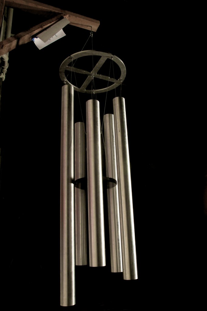
A while back I bought five 4.5 foot long aluminum tubes because the price was so low that I couldn’t resist. They are 3.25 inches in (outer) diameter, and have a wall thickness of 0.1 inches. Recently, I decided to make them into the longest and loudest wind chimes I’ve ever heard. The longest tube rings for over a minute after being struck by the clapper. After thinking for a while about which notes I should tune the tubes to, I found that fairly large chimes are commercially available, but they are tuned to happy, consonant intervals. I consulted a few musically savvy friends (Thanks Brian and Andrew!) to gather some more ideas for interesting intervals on my chosen theme of “Evil & Ominous.” I ended up with quite a few ideas, and with Andrew’s help, I sampled the sound of the longest tube being struck, and recorded mp3’s of each set of notes to simulate the sound of the chimes ringing in the wind. I ended up with something delightful: D4, G#4, A4, C#5 and D5 (which are 294 Hz, 415 Hz, 440 Hz, 554 Hz, and 587 Hz). That’s right, there are two consonant intervals (octave and major 5th), but look at all those minor seconds and tritones: Delightfully Ominous!
Then the science started: How to determine the tube lengths to achieve the desired notes? How to suspend the chimes so they sound the best, and are the loudest? Where should the clapper strike the chimes in order to produce the loudest sound or the best timbre?
Wind chimes radiate sound because they vibrate transversely like a guitar string, not because they support an internal acoustic standing wave like an organ pipe. Pages 152 & 162 of Philip Morse’s book “Vibration and Sound” show that the natural frequencies, v, of hanging tubes are given by the following expression:
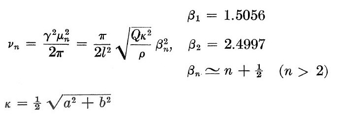
Pretty simple, right? One only needs to know rho and Q, the density and Young’s modulus of aluminum, l, the length of the tube, a & b, the inner and outer radius of the tube, and the beta of each tube mode of interest. Don’t worry though, there is a simpler way. If all of the tubes have identical diameter and are made of the same material (6061-T6 Aluminum!), the equation indicates that the natural frequency of a hanging tube scales very simply as the inverse of the tube length squared.
Using the above relationship (frequency ~ 1/(length*length)) to compute the ratios of tube lengths based on the ratio of frequencies produces:
Length of D4 tube = 1.000 * Length of D4 tube
Length of G#4 tube = 0.841 * Length of D4 tube
Length of A4 tube = 0.817 * Length of D4 tube
Length of C#5 tube = 0.728 * Length of D4 tube
Length of D5 tube = 0.707 * Length of D4 tube
The longest tube is 133.1 cm (52.40 inches) long, so all the tubes were scaled relative to it. Note that the frequencies are slightly different than the notes I was aiming for, but absolute pitch is only a requirement when playing with other instruments.
~D4 = 293.66 Hz = 133.1 cm = 280.3 Hz
~G#4 = 415.3 Hz = 111.9 cm = 396.4 Hz
~A4 = 440.0 Hz = 108.7 cm = 420.0 Hz
~C#5 = 554.37 Hz = 96.9 cm = 529.1 Hz
~D5 = 587.33 Hz = 94.1 cm = 560.6 Hz
How accurately do these tubes need to be cut? For example, how important is it to cut the tube length to within 1 mm? This can be calculated simply, using the above equation. A length of 108.7cm gives 420.0 Hz, whereas a length of 108.8cm gives 419.23 Hz. This spread is 0.67 Hz, which is a fairly small number, but these small intervals are often expressed in cents, or hundredths of a half-step. This 1 mm length error gives a frequency shift of 31cents. Does this matter? Well, the difference in pitch of a major third in just and standard tuning is 14 cents, which is definitely noticeable. It is preferable to be somewhat closer than this 1mm, or 2/3 Hz to the target interval.
The tubes were rough-cut to 2 mm longer than the desired length on a bandsaw to allow the ends to be squared up in case the cut was slightly crooked. The resonance frequency was then measured by playing the desired frequency from a speaker driven by a sine wave generator with a digital display. I then struck the tube and listened for (and counted) the beats. If two beats per second are heard, the frequency of the tube is 2 Hz different than the frequency played through the speaker. With this method using minimal equipment, I quickly experimentally measured the resonance frequency to less than 0.5 Hz (one beat every two seconds), which is ~10 cents. I then fine tuned the tube length using a belt sander, and measured the resonance frequency several times while achieving the correct length. In reality though, if I missed my target lengths I’d only be adding a little more beating and dissonance, which might have only added to the overall ominous timbre.
How to suspend the tubes? Looking at the mode shapes of the tube for guidance, I suspended the tubes by drilling a hole through the tube at one of its vibrational nodes, and running a plated steel cable through it. Check out the plot below from Blevins’ New York Times Bestselling book “Formulas for Natural Frequency and Mode Shape.”
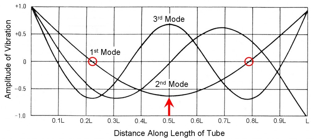
This plot shows a snapshot of the tube’s deflection as a function of position along the tube. Imagine that the left side of the tube is at 0, and the right side of the tube is at L. This plot shows the first three mode shapes of a “straight slender free-free beam,” which my 1.33 meter long, 83mm diameter tube qualifies as. Just like a guitar string, this tube has multiple overtones (higher modes, or harmonics) that can be excited to varying degree depending where the clapper strikes the tube. The guitar analog of this is the timbre difference one hears when picking (striking) the string closer to or further from the end of the string (the bridge). This plot also shows where the tube should be suspended – from the locations where the tube has no motion in its first, fundamental mode. Those two places, a distance of 0.221L from the tube’s ends, are circled in red. When striking the tube suspended from either of these locations, the tube rings the loudest and for the longest time duration (as compared with any other suspension location). Similarly, when striking the tube in the location noted by the red arrow (the midpoint of the tube), the tube rings the loudest. I won’t get into more math and fancy terms like “modal participation factor,” but it is true that suspending the tube from the circled red locations also results in the lack of excitation of the third mode (which has a motional maximum at this location). Similarly, striking the tube at its midpoint results in the lack of excitation of the second mode, due to its motional minimum at this location.
Thanks to David for the Ominous Photo. An Ominous Chime video will soon follow.
Awesome! I’d love to hear the Ominous Chimes some day. I don’t suppose their size/weight lends themselves to portability though.
-Mike
We should shoot an ominous video with a good microphone so everyone can see and hear it too!
it is really looks wonderful great peace of work done……the graph highlight the whole matter …great work
Where did you get the tubes? Please email me.
Thanks
The tubes came from a scrap yard.
I’d like to know where you got the tubes as well. I have an old, expensive, windchime that has a sand cast bronze top that has five hanging points. The tubes hang between the points on string. One tube is missing and must be replaced. The clapper is missing as well. The remaining tubes are 14 3/4, 13 3/4, 11 3/4, and 11 3/4 All are hung at the same height. I assume the missing tube is 12 3/4 or 15 3/4. What would be your guess? The o.d.of the tube is 3/4″ and I think they are copper and not bronze. I could be wrong, they are heavy. They have copper colored patina.
Based on those tube lengths, it looks as though your chimes were designed for their visual beauty rather than being tuned to form a particular series of tones. It may prove difficult to find a replacement tube of the same color and patina as the other tubes.
Hey KevinB…Wheres the video and sound of these? Please post a link!!
I am in the process of building a set from 6″ diameter, .120 wall tube with one at 18″, one at 16″ and one at 14″. I would like to know if there is a way to modify the tone emited by sliting the tube a given length, say 4″ or by some other means, maybe cutting a section from the bottom? Anyone tried this?
If you look at the Blevins mode shape plot and apply some physics, the answer comes back: Add mass to the ends of the tubes, in an axis-symmetric way. This can be done by attaching steel masses inside the tube via holes tapped through the tube wall. Alternately, reduce stiffness at the velocity nodes (0.221L and .779L) in an axis symmetric way. Thus can be done by drilling holes (or making slots) with even spacing all the way around the tube at a distance of 0.221L from both ends. Note though that your tube is too short to be accurately modeled by the equations shown in the post, so adding mass at the ends is the better of the two approaches.
[…] wood, beer, water, whisky, fire, arduino, welding, odd, audio, casting, and numerous acoustic projects that I’ve worked on at the Makerspace, I’ve finished a few electronics […]
[…] [1] http://milwaukeemakerspace.org/2011/09/giant-ominous-wind-chimes/ […]
Liked your write up. Do you make large wind chimes for sale?
Bill
Unfortunately, I don’t. But I would be more than happy to answer any questions that arise when you make your own!
Kevin, I was looking at your write up and thinking about making a different chord, and I noticed that the frequencies in your documentation don’t match with what I usually see referenced. E.g., A4 is 440 Hz, and you have it as 420 Hz. Also D4 is normally 293.66, and you have it as 280.3. I see you have those numbers marked out, so what piece am I missing?
Thanks!
Norman
Norman,
I didn’t want to cut my longest tube to be shorter, so I scaled all the tubes relative to the longest one. Note that made the frequencies slightly different than the pitches I was originally aiming for, but absolute pitch is only a requirement when playing with other instruments.
Kevin,
Will the same formula works for galvanized steel conduit? 4″ diameter.
Thanks
I want to make a few wind chimes. I need to find the pipes. Jdfento@gmail.com
John, I’d recommend buying local & surplus, but if not… ….http://www.mcmaster.com/…
Hi. I’m about to build a really big wind chime and I was wondering, if I started with an 8 ft pipe (1 1/4, IPS 6061T-6 aluminum) and kept the same ratios as you describe, would I still have the ominous sound?
Teddy, you’ll definitely have that same ominous sound if you use the length ratios shown above. In addition, you’ll have very low pitch chimes, as the tubes are both longer and smaller diameter! When you’ve finished building it, definitely post a video of how they look and sound and share the link in this comments section! Happy building, and feel free to contact me with any more questions you have!
I am trying to find a place in Milwaukee area to buy the pip e ss
Perhaps you can find them at scrap prices, from Harrison Metals at 35th and Montana (414) 333-6896. Otherwise you can buy retail locally, at speedy metals.
Kevin,
Thanks for the write-up, your research was really helpful in my own build. One thing I wanted to mention to other readers who may be getting ready to make their own chimes – I found that the method used to hang each pipe can have a significant effect on the sound of the pipe as it is struck. I drilled at the nodal point as you did, with good effects. The hanging method could change volume, duration of the ring, and pitch depending on what I tried. If the pipe comes in contact with the cable/string of the traditionally centrally suspended pipe it can damp the sound, lowering volume and shortening the time the chime rings – possibly a pro depending on what you are going for. The best way to get loud and long rings based on my experimentation was to avoid any contact with the pipe other than at the cross-drilled hole, and even then to make that contact the type the would be difficult to transmit vibration (damping in this case) through. I used a .060 weld rod with 1/4″ OD polyethylene pneumatic tubing over it as a sleeve. The cross drilled hole was 1/4″ also. This gave a secure method to hold the pipe, but had the least effect on damping out the ring.
where can I purchase these ominous wind chimes?
Thanks for the excellent report, or article. We came across huge chimes in Los Alivos, California this weekend and immediately decided to build a set for my 40′ sycamore tree. I have been all over the web, but your article gave me the insights I needed. The nodes info was priceless. Where do I get 0.1″ walled aluminum tubing?
Hi. How do you determine the size of the hole for the suspension point?
The hole size is arbitrary, and does not really affect the sound radiation, if it is located as described above.
Hi, Kevin.
I used the formula shown and the 108.7cm length and I get 429.895Hz.
What did you use for density and Yound modulus?
Thank you.
Hellow, Liked your article and idea. Do you make large wind chimes for sale? Or any place I can buy such big chimes online?
We do not sell them, but you might be able to find a member you can hire to build you a set.
Purchased 8 ft by 2 inch brass tube from Habitat for $10. Was originally a $300 bar foot rail.
Purchased brass headboard and footboard for a double bed $35. Really old, beautiful patina and fittings.
Hint: Shop with a magnet.
Several people ask where to buy large chimes. . I sell giant wind chimes. If anyone is interested please email me. I make them so they can be disassembled easily and replace parts as the weather. Makes it easier to ship too.
tater7114@gmail.com is my email
Tune chimes to e lydian 7#11 chord e,g#,c#,d# A# Octave/8th, make another set tuned g# minor 7 g#,b,d# f#.. harmony = Spacey lydian tonality and aeolian natural minor melancholy tonality.. sounds ethereal, and trippy, kinda like call and response.. harmonized communication. Parallel modes like c major stacked with c minor sound pretty cool as well..
i am looking for the perfect chimes for my living space. could this be it? i want to hear the chimes!
I have some 3″ diameter bamboo that is cut to different lengths. The bamboo has been sitting for a couple of years in a shed. Do the joints have to be reamed out? Can I leave the tubes intact or should I think about scalloping the bottoms?