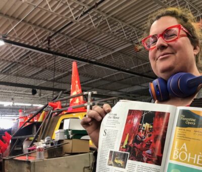
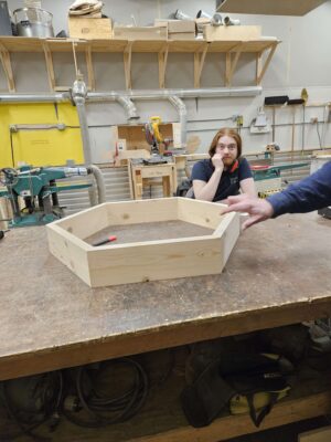
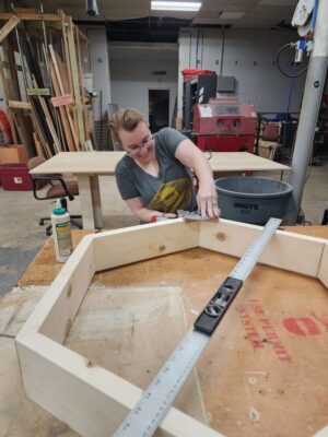
Its always been a joke here at the Makerspace about how so many members use the lasers and 3D printers to make their own Settlers of Catan games. A few months ago, I noticed that somebody was cutting out giant hexes on the BOSS laser for a larger Catan game, giving me an idea for a back yard Catan. I mentioned this in the laser group, and the idea just exploded! Multiple people expressed that they wanted to instead do a group project of having a GINORMOUS Settlers of Catan game. After several weeks of meetings, we decided on hexes that are 3 ft across, making our entire board 30 ft.
In the last 2 weeks, we have begun building our prototype, and we are ready to start production of the remaining hexes.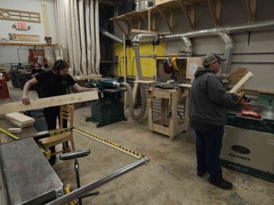
We had to start out with cutting down a 2x6x10 board into 6 pieces and joining and plaining them to all be the same thickness
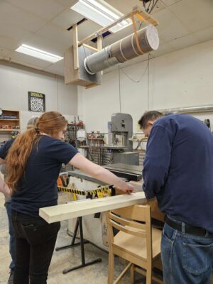
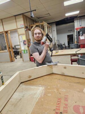
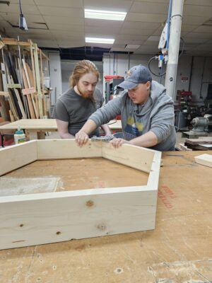
Greg Waldo then taught us how to use a table saw to cut the grooves into the top rather than using a router. This made things much faster and accurate. 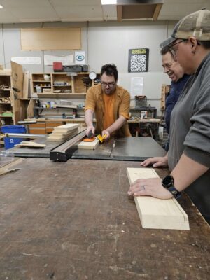
We tried to use pocket hole screws, but they did not work very well.
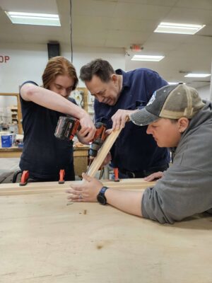
In the end, we opted for a good old fashion glue up and finish nailing.
The goal for this project is to be able to have it finished in time for Milwaukee Makerfaire! Stay tuned for more updates. We are always looking for more people to join us, every Monday! Upcoming Mondays we will be meeting at Norwich to use the Norwich woodshop!