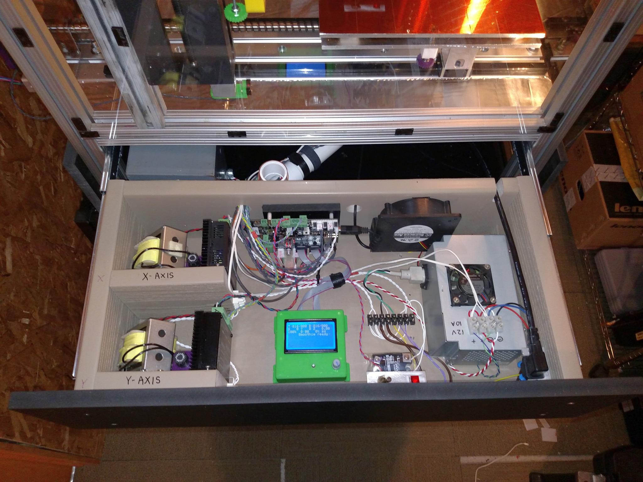
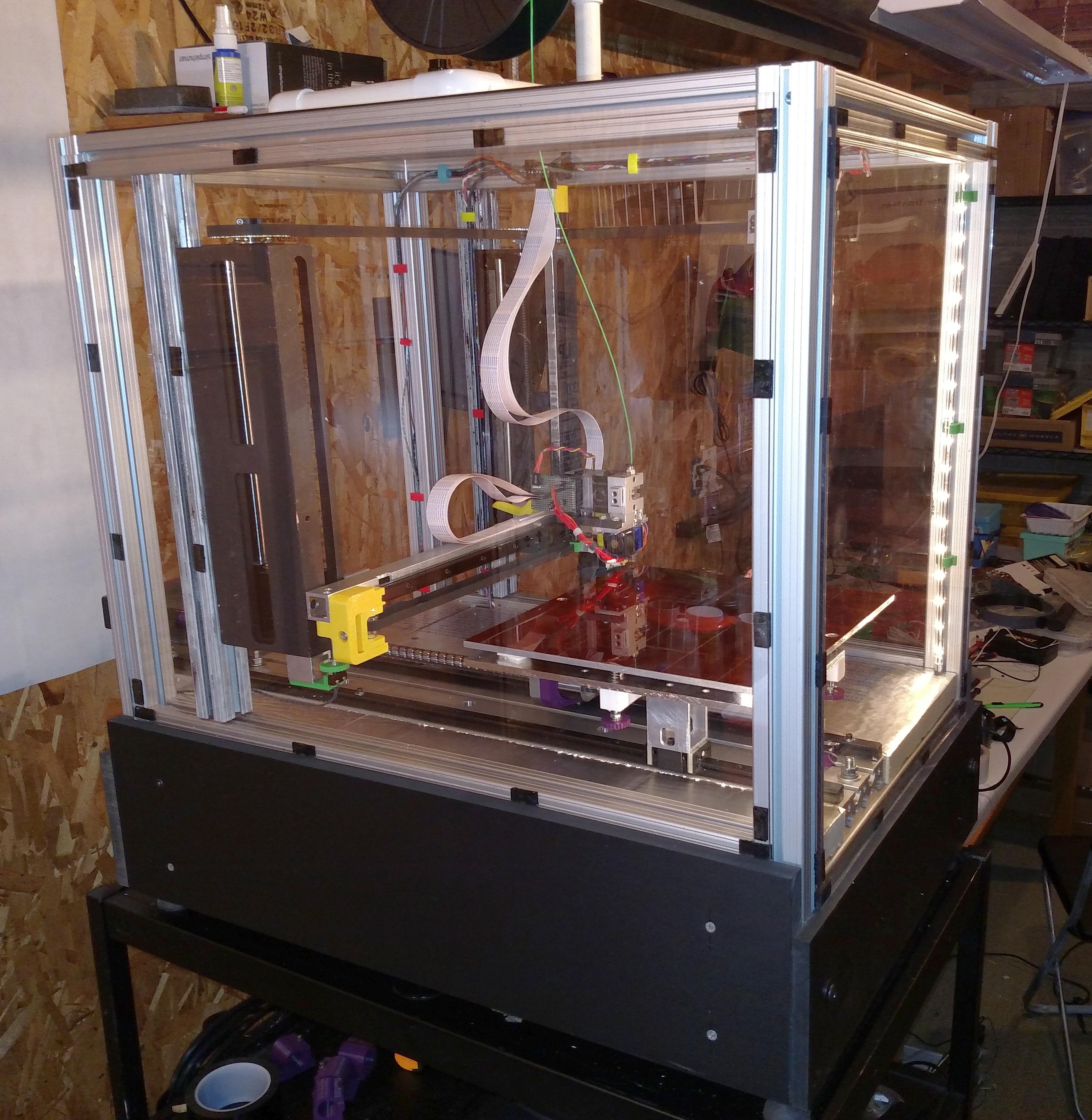
Chocolate printer progress continues. This week was devoted to the print cooling system. The chocolate will come out the extruder nozzle in a semi-molten state. It needs to solidify by the time the next layer of chocolate gets deposited on it, and I’d prefer it doesn’t drip or sag, so it needs to be chilled right after extrusion. The current plan is to blow chilled air over the chocolate just after it leaves the extruder. The chilled air will come from a foam insulated box containing a block of dry ice. There will be a blower pushing air into the box and a hose delivering the chilled air/CO2 to the print.
A couple weeks ago I got a blower from American Science and Surplus and this week I got it running by using a model airplane ESC and servo tester to drive its brushless DC motor. It appears to be capable of blowing much more air than I’ll need. There are many unknowns yet to test. How much chilled air/CO2 will it take to solidify the chocolate after it leaves the extruder? How long will a block of dry ice last when used this way? Will ice build-up inside the chiller box adversely affect its performance?
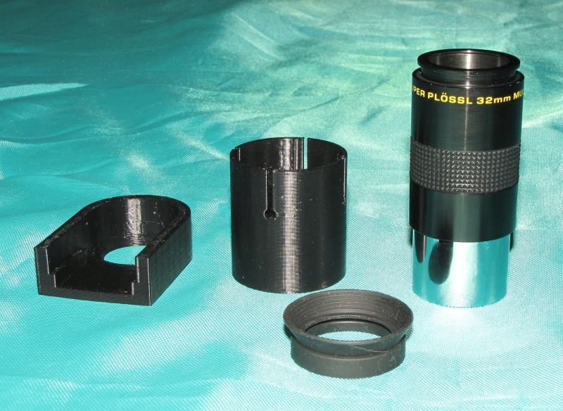
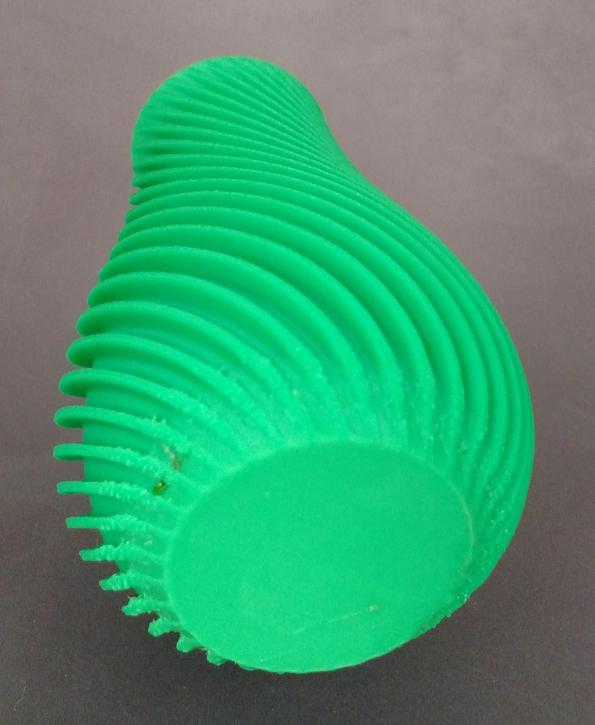
I designed and printed three parts for this system- a mount to attach the blower to a foam box up to 1.5″ thick, a hose coupler to allow delivery of the chilled air/CO2 to the print, and a hole saw to cut holes to fit the other two parts. The printed parts fit as if they were designed for the job!
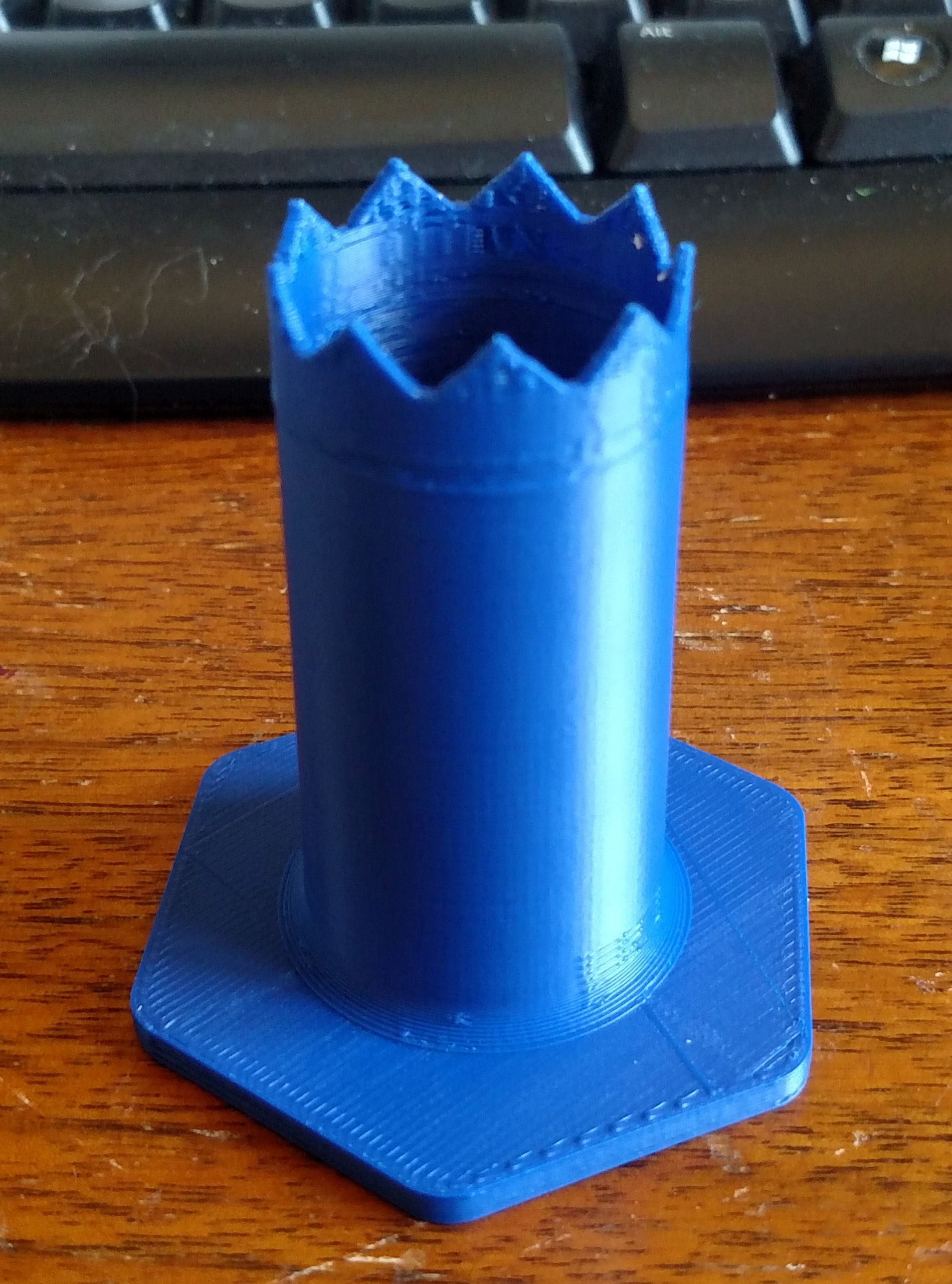
3D printed hole saw
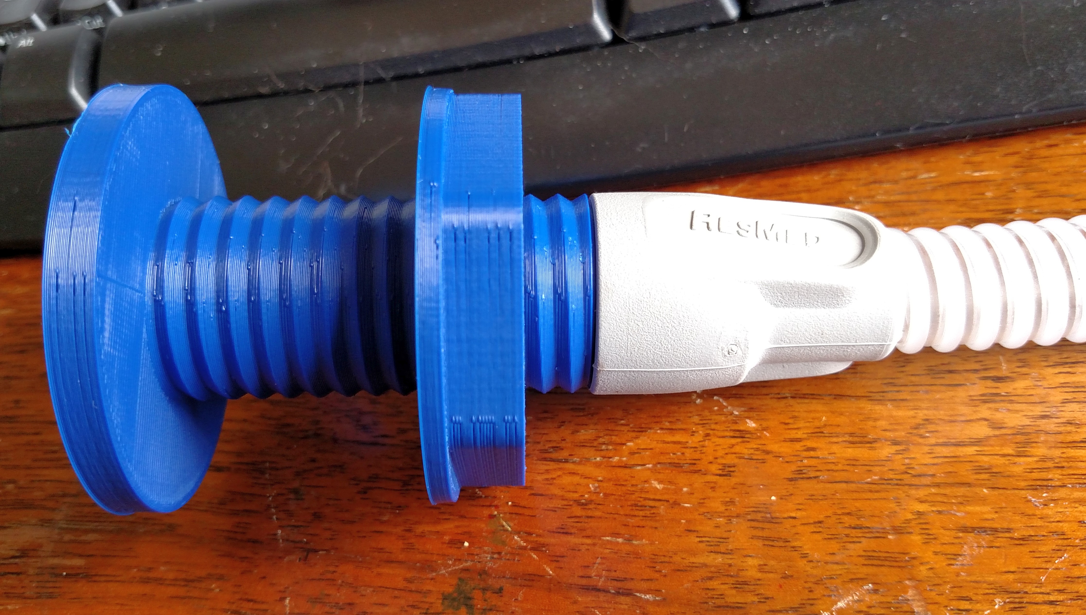
Hose connected to hose coupler
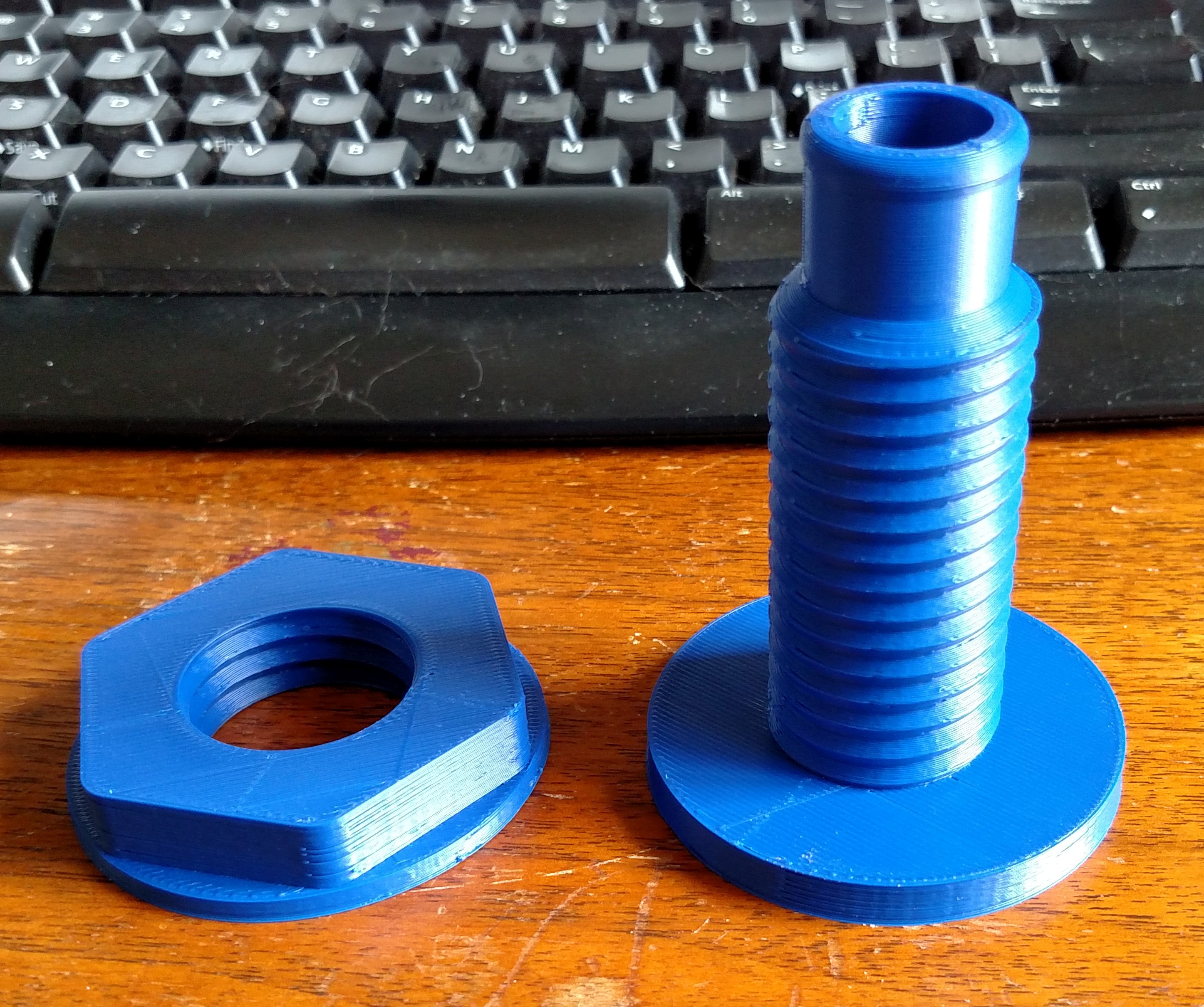
Hose coupler parts

Blower mount for air chiller box