Tie Pin PCBs!

The tie pin PCBs came in and they look great! We’ll use these PCBs to teach folks how to solder and spread the word about Milwaukee Makerspace!

In the photo above you see two identical boards each showing the opposite side. On the logo side two flashing rainbow LEDs go into the eye sockets and two current limiting resistors go to the left and right of the welder’s mask. On the back side, near the bottom of the pcb you can see two large rectangular pads that bracket a very large circular pad. The feet of a surface mount coin-cell battery holder that goes up and over the circular pad are soldered to the rectangular pads. The resulting cavity is a perfect fit for a standard CR2032 coin cell battery. Near the top is an oval shaped pad where the tie pin is soldered down.

Whenever we offer a Learn to Solder session at an event we’ll have these PCBs and associated electronic components in kit form available in exchange for only the time and effort required to learn to solder one together. (Small donations are appreciated, but in no way required) Most folks take less than 10 mins to master the basic soldering technique and are rewarded not only with a flashy tie pin or broach but also with a newly opened door to possibilities by virtue of their new ability to construct electronic circuits.
RN-42 Carrier Board

image

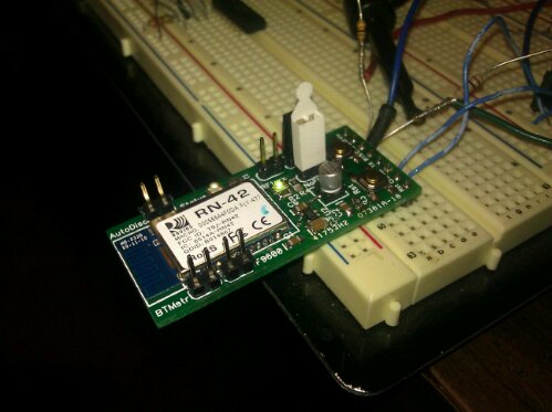
I got that RN-42 carrier board populated and working! Its ready for the GyroSkirt driver board, once I get that built.

There are a few errors on the board. TX and RX are swapped somewhere. Either on this board or on my USB to TTL-Serial board or in the RN-42 documentation. Also it seems the LEDs were meant to go to Vcc rather than ground. As a result my LED indication for connection status and RF traffic is inverted.

I can live with the errors as the actual data transmission works like a champ. To test the tranmission I hooked the carrier board up to a PC via a USB to TTL serial converter configured to operate at 3.3V.  The venerable Hyperterminal program was used to open the virtual com port on the PC. Then I downloaded Sena’s Bluetooth terminal program to my Android phone and used it to form a Bluetooth serial connection between my phone and the modem. The result: keys pressed on my phone’s keyboard appeared inside the Hyperterminal running on the PC and keys pressed on the PC keyboard appear inside the Sena Bluetooth terminal running on my phone. Bi-directional data flow at 115,200 baud.

Now that I have proven my wireless link works, I need to update the GyroSkirt/GryoBelt firmware to allow me to adjust the gain and the deadband over the Arduino’s serial port.  (In addition to actually making a driver board that has a spot for the modem.)

iTead Boards

image

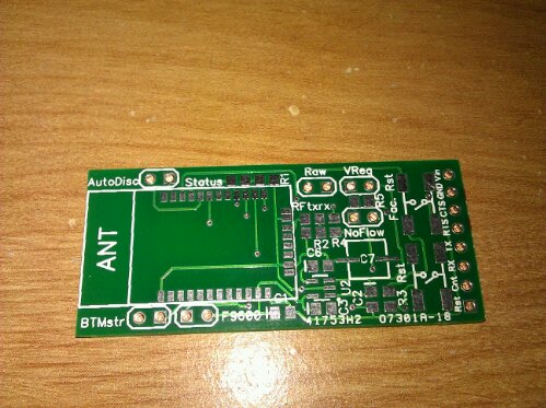
I got my first batch of iTead Studio boards in!  iTead Studio is a  pcb printing shop that offers absurdly cheap prototype boards. The new boards look great. I’ll definitely use them again. It only took 2 1/2 weeks to get here. For the price its an awesome service.

The particular board shown is a carrier board for the RN-42 Bluetooth modem, which is only $15 from Sparkfun if you buy it in its surface mount form. For another $15 I now have 10 12! carrier boards that allow me to adapt the surface mount device to through hole technology as well as control infrequently utilized device specific features such as factory reset, BT Master mode, force 9600 baud and more. The more you know the cheaper electronics gets.

The carrier, populated with the modem, etc., is destined for the GyroSkirt. The idea is that I’ll be able to adjust the gain and deadband processing on the gyro sensor reading wirelessly from a program on my Android phone via the Bluetooth radio in my phone and one of these boards affixed to the GyroSkirt driver. The GyroSkirt will again be driven by an Arduino,  so I hope to leverage the Amarino library to speed my development time.

Screeching Cat Railing

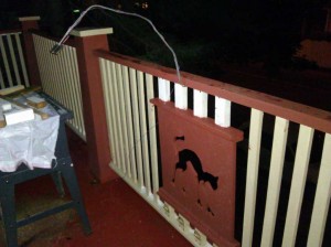
CNC Cutout of screeching cat inserted into porch railing

Recently we completely re-built our aging 2nd story porch. During the process I took the opportunity to add a little flair courtesy of the makerspace’s CNC Router. The idea was to place an emblem into the railing of the porch as decoration. After thinking about the emblem I’d want I decided that I’d never be happy with just one, so I incorporated spring hinges (look carefully below the cat in the photo) that allow me to pull back and replace the emblem at will with ease. With that done the only thing to do was decide on the first emblem. I decided on seasonal/occasion emblems.

Rich showed me a great site with free CNC artwork, some of which was Halloween themed. I downloaded that artwork, selected the screeching cat and had the CNC router cut the cat out of a 2’x2′ plywood. I installed the cat as part of the porch railing as you can see in the photo.  I’m now looking to round up a turkey for Thanksgiving, a snow man for winter, etc.

During the design process TomG had the bright idea to shine a light through the cutout. So I took a high brightness LED out of a malfunctioning flashlight and attached it to some sheet metal on a malleable aluminium boom. The result is that I now have a screeching cat projected down onto the sidewalk below. (It’s too dim for me to capture on camera)

I’m really looking forward to cutting out more shapes on the CNC Router!

ARM Investigations

image

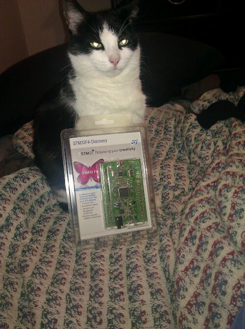
My cat has been telling me she wants to get more into 32 bit ARM processors. So when ST started freely offering their discovery development board for their new Corex M4, I jumped at the chance. My luck was in and the board arrived today! The STM32F4 on the board has a full meg of flash and a single precision floating point unit! Oh and like a bazzilion hardware timers and lots more. The board itself has a number of sensors and a big LED on it.

My cat is looking forward to spinning up a compiler and putting the device through its paces. She is especially looking forward to the demo app where the board pretends to be a mouse.