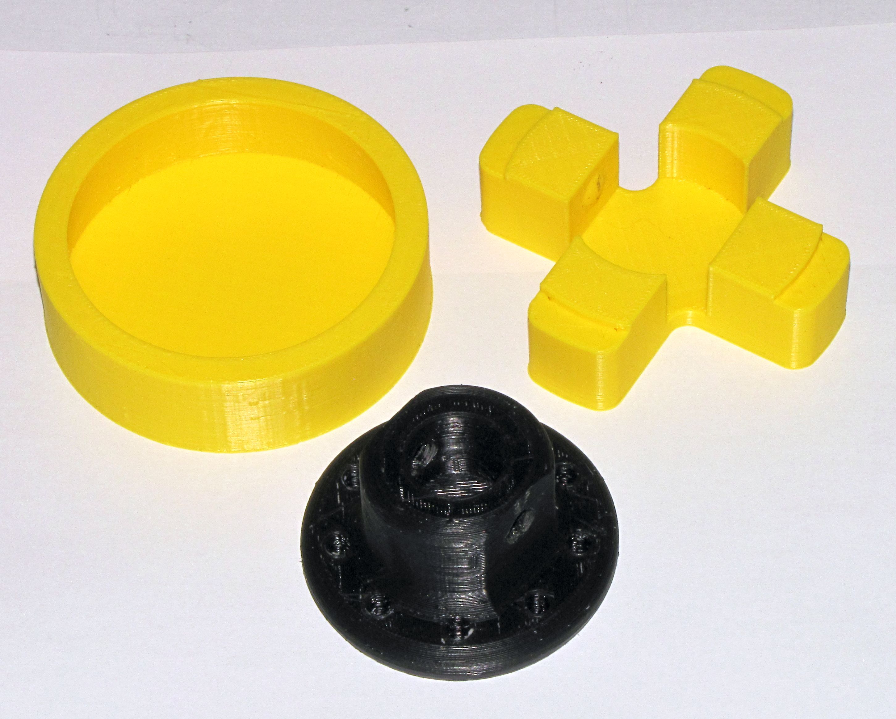
My last post showed how I made a plunger for a 3.5 liter syringe. Today’s post is the results of the first ever test of that syringe assembly including the plunger. The goal of the test was to determine if the syringe pusher would be able to push very thick, viscous paste (sort of like melted chocolate) out of the 1/4″ syringe nozzle. It was also a test of the ability of the previously made silicone plunger to maintain a seal even against whatever pressure develops inside the syringe as it is pushing.
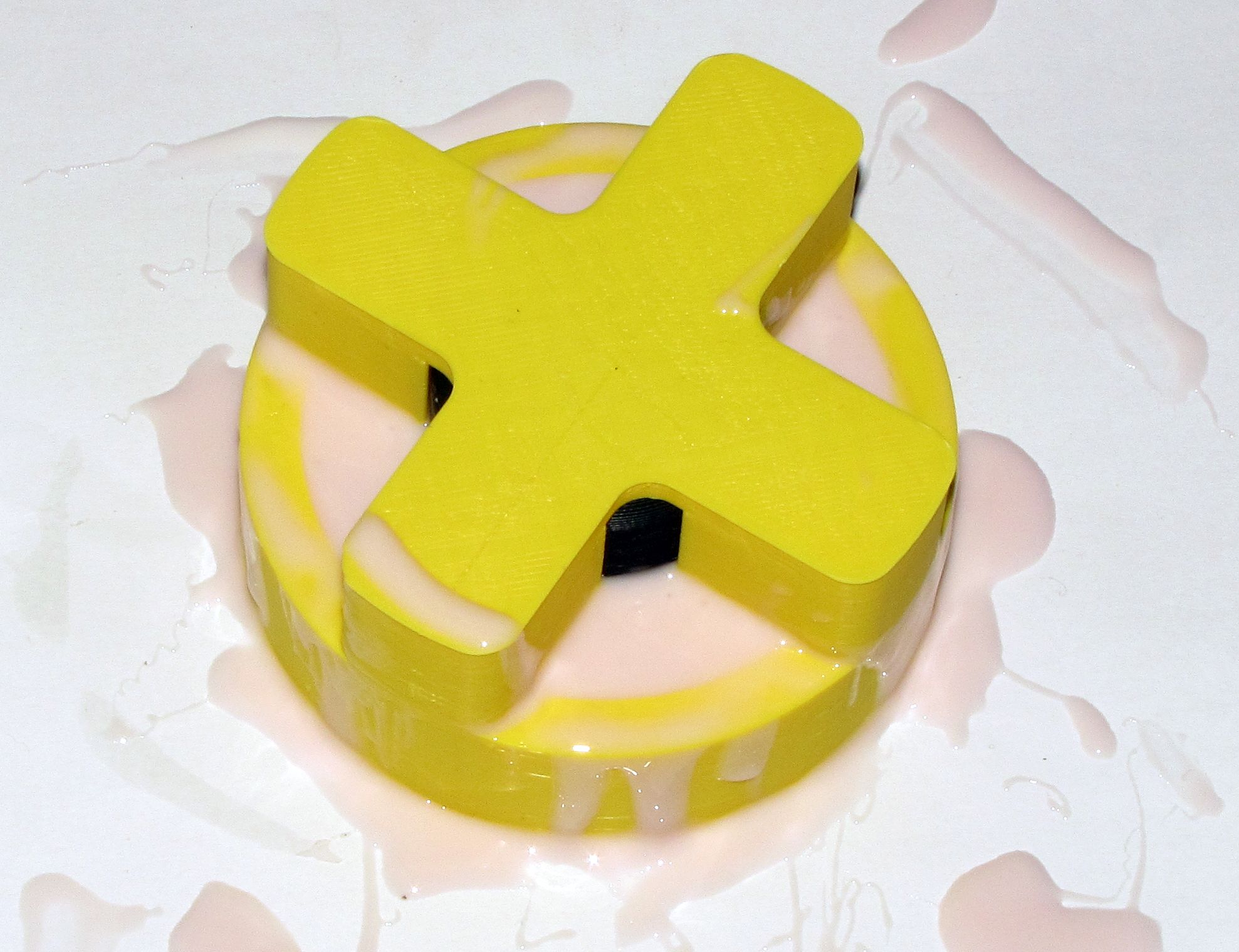
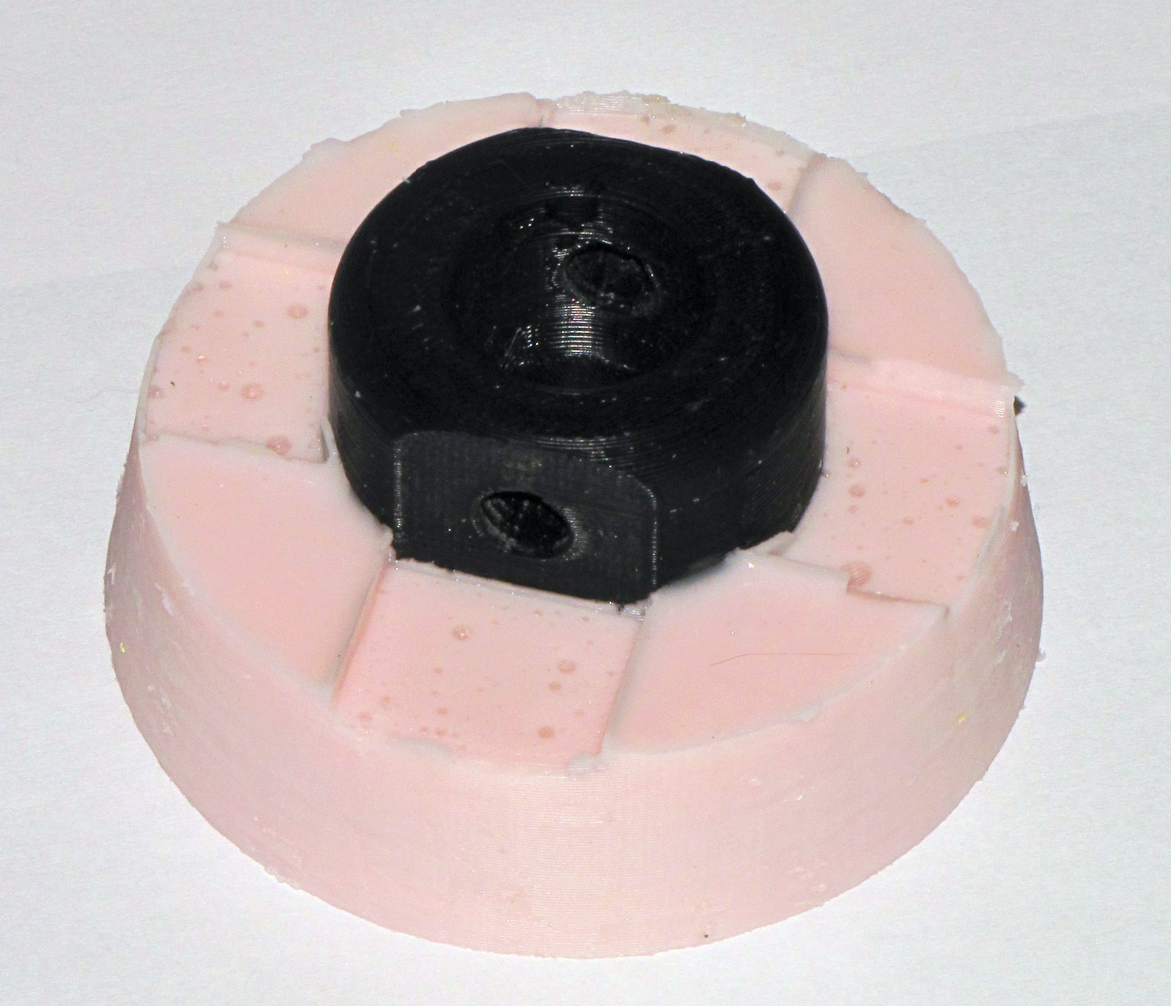
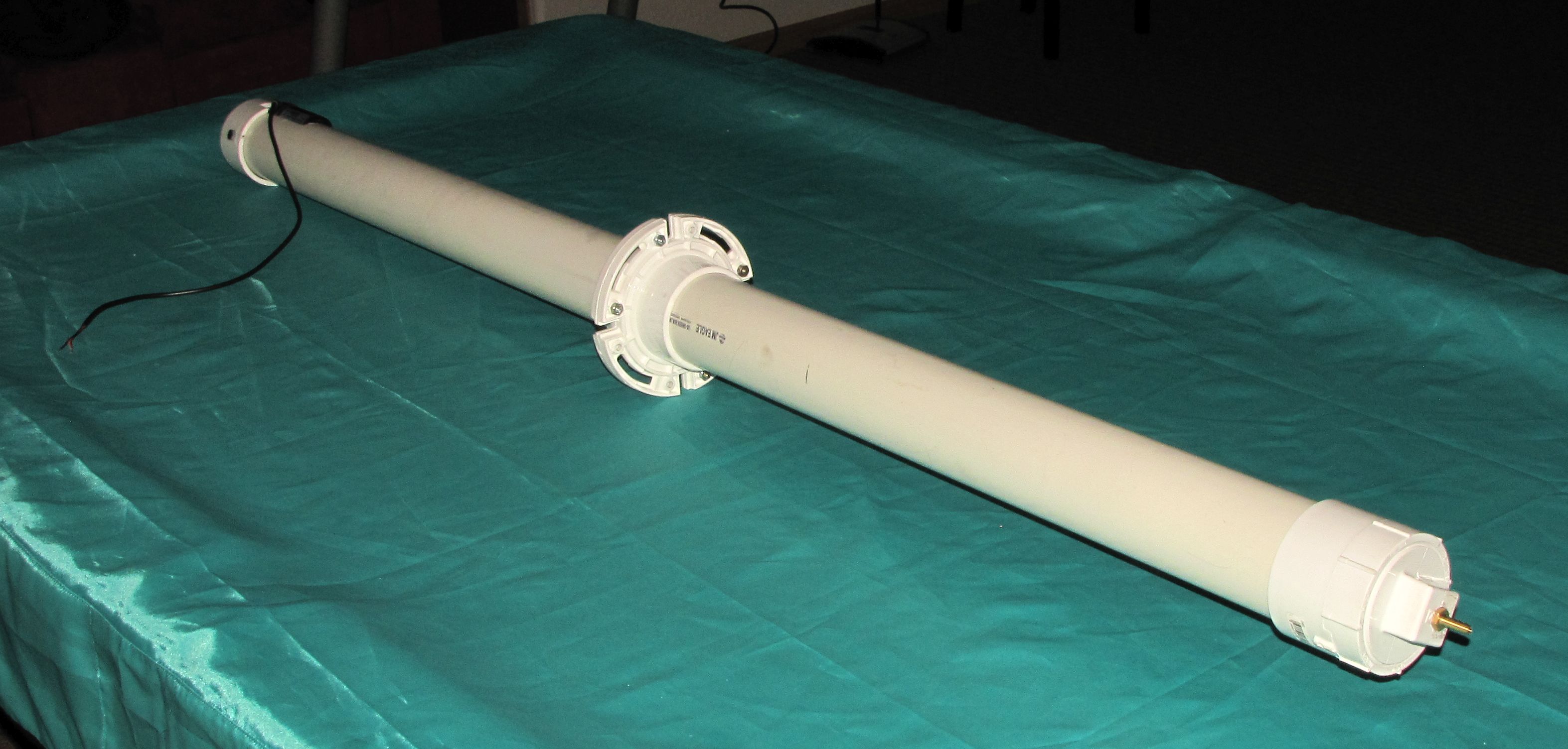
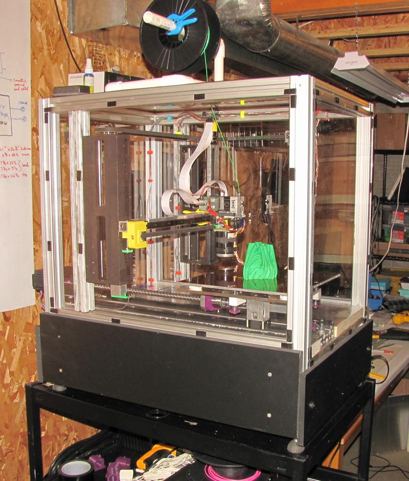
I mixed about 1 liter of extra thick pancake batter to a consistency that I thought would be much thicker than molten chocolate (pancake batter is much cheaper than chocolate) and shoveled it into the syringe, then bolted on the pusher and hooked it up to a power supply:
Looking back, I probably should have loaded the syringe from the other end.
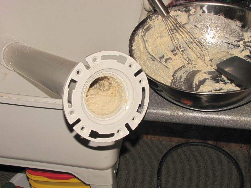
Syringe loaded with super thick pancake batter.
Here’s the actual test. It gets especially interesting about 1 minute in:
The syringe continued drooling after power was removed due to air that was trapped inside the syringe. As the plunger pushed, the air was compressed. When the motor stopped the compressed air continued to push out the batter. I will have to be careful to eliminate air bubbles in the material when it comes time to use this in a printer.
It only took a couple minutes to clean out the syringe after the test was done.
The pusher did its job much better than expected, and the plunger held up just fine, too. I feel confident that this device will be able to extrude chocolate. Now the real work begins…