My electric Dodge neon uses an AC motor and an industrial motor controller. I upgraded from m 1984 motor controller to one less than 25 years old (actually less than 5.)
The new controller does much more than the old one and has the ability to do some fancy tricks. At the moment I am running it in “sense vector” mode. The controller senses the position of the armature by monitoring the current in the field coils. This works great… as long as the motor is spinning. From a stop it tends to get out of sync, but there is a cure!
The controller can use a quaderature encoder so the encoder can read the position of the armature at any speed.
To add an encoder to the motor I decided to try a chip amde by Austrial Microsystem AS5040. This chip senses a magnet near the chip and calculates the position of the magnet and can generate multiple output: PWM, binary via I2C, and quadurature!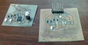
I bought a few of the chips and built a surface mount board to hold the chip and a few LEDs to display the output. The first two version had a few problems but the 3rd time was the charm.
Thanks to Royce for working out the process for surface mount PCBs.
The fina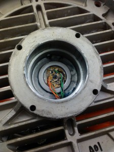 l version had to be small enough to fit in a depression in the end of the motor cap. The sensor centered and the whole board insulated (clear enamel) since this is a grease pocket
for the rear motor bearing.
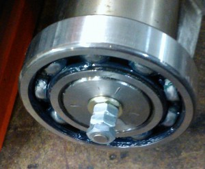
The magnet is mounted to a bolt that is threaded into a tapped hole in the back end of the armature. It took a while to the position right (it needs to be within a few millimeters of the sensor) hence the nuts and washers.
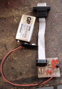
The cable is brought out of the motor through a small threaded hole (it was an alternate location for the grease fitting.) The hole is filled with epoxy and the wires go to a DB9 connector. I built a small test board that shows the quadurature signals (4 round LEDs) and the status outputs from the chip (the two rectangular LEDs)
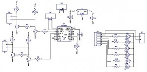
The motor controller puts out 15V to power an encoder and wants A and B as well as inverted A and B signals. The circuit includes some NPN transistors along with a voltage regulator and a few capacitors to tie it all together. I put the schematic for both the sensor and test board on one schematic so I could make both boards at the same time.
I installed it in the car today, but still need to put a few more parts together to run it.
DOH!
It doesn’t work!
Ok, so the electronics work fine, it talks to the controller.
But it tops out at 256 pulses per revolution and the controller needs 1024. It was a minor confusion between terminology. The sensor detects 1024 positions, but to generate quaderature it uses 4 positions per pulse output.
Back to the drawing board.
I picked up a commercial shaft encoder on ebay for 50 that outputs 1024 PPR but it only works at 5V, so I’ll need a level shifter board and connector adapter.
Oh, yea, and I need to put the motor again, take out the old encoder, bring a shaft extension through the back grease pocket, add a grease seal and couple it to the encoder.
I have bought a controller from china brand slider I installed it in my car but it does not work, the motor turns slowly and the controller heats up, they told me to reverse 2 phases of the motor and it remains the same then I tried with the program to make changes in the number of pulses of the encoder and everything remains the same I don’t know what else to do I need help
Raul, there are a number of parameters that the encoder needs to have to work with a given controller, number of pulses, type of signal, etc. Then you need to set a number of parameters on the controller to match the configuration, motor poles, RPM, encoder type and PPR, etc. You may need to consult a servo motor expert or just try lots of different configurations. No easy solution I can give you.