by: Tom Gralewicz
I’ve got a problem
The battery operated projects I have been working on lately are using higher voltages. In the past my projects were 12 or 24 volts, now they are 36 to 48 volts.
The problem is when I want to put an indicator to show the status of power, a motor controller, BMS, etc. In the past I would have just used an LED and resistor. Now that doesn’t work as well:
At 48V, a LED with a 2.5V drop drawing 20ma would need a 2,275 ohm resistor.
A 2,275 ohm resistor dropping 45.5V is dissipating 0.91 watts! I would need a 1 watt resistor and 95% of the power would be wasted in the resistor – not good in a battery operated environment.
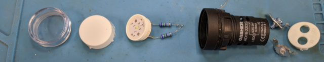
The fact that this is the approach taken by the 24V panel lights you can buy is obvious by the two ¼ watt resistors and vent holes in the body of the light:
So what do I do?
Well, I could use all that extra energy to light more LEDs:
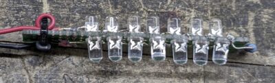
Cool, but now it needs a minimum voltage to light up and I don’t really need something that bright to show the status of a fuse or battery.
What I really want?
A single or dual LED that lights up from 5V to 50V, I don’t want to use different resistors for each voltage, I don’t want to worry about the LED getting too much current and burning out or the circuit drawing too much power and draining my batteries.
A Cheap Universal LED Driver – CULD
So I started playing with pulsing circuits, something that would pulse shorter and shorter as the voltage went higher. Too bad my analog design skills are really bad, because I failed.
Along the way I found a simple chip in a TO92 case that was a linear current regulator, preset to 25ma. The CL25N3 https://www.microchipdirect.com/product/CL25N3-G
Less than 50 cents each, 90V max input, it provides constant current for any input voltage.
Except that it operates as a linear regulator – so it acts like a resistor to drop the extra voltage and with a maximum power of 0.6W it would cook at 48V driving a single led.
What I really want is a small, inexpensive switching regulator. They make them but their idea of inexpensive is $3 for the chip plus all the extra components.
Then one day I stumbled across a chip from TI, the LV2862XLVDDCR, at $0.15 each in quantity 1000.
https://www.ti.com/product/LV2862/part-details/LV2862XLVDDCR
Add in a few extra components, feed the sense line with a current sense resistor instead of a voltage divider and poof! A low cost, broad input range, current controlled LED driver.
Select the correct R2 and this circuit will drive one or more LEDs from 1ma to 600ma, from 4V to 60V input. Note: minimum input voltage is the voltage drop across the LEDs plus 0.765V with a minimum of 4V.
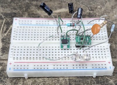
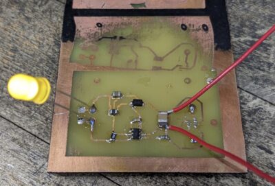
I built this circuit on a bread board with some SMT break out boards:
Then I etched a circuit board and used all SMT parts to make sure I had it right:
After a little thought I added a bridge rectifier on the input so it could handle AC or either polarity DC.
I’ll explain the choice of bridge in Note 1. And room for some SMT LEDs as well as through hole and…
What I wanted all along!
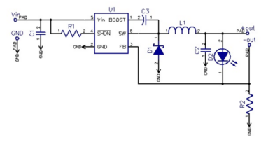
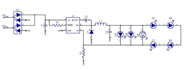
Here is the current schematic:
(Yes, 7 LEDs see “But why call it universal?” below)
The boards are tiny, 0.71×0.35”:
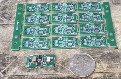

And the circuit is single sided, Note 2:
And they work great:
But why call it universal?
The list of configurations is endless:
- Single SMT LED on the front
- Single SMT LED on the back
- Parallel SMT LEDS one front, one back
- Through hole LED on either side
- 1 to 4 series SMT LEDs on the back
- Single off board LED – up to 600ma
- Multiple off board LEDs, 600ma and total voltage > Vin – 1.4 (Vin 4V min) Note 3
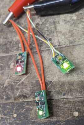
Multi LED:
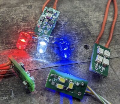
The top CULD is driving 3 different color LEDs in series, left module has a SMT LED on each side of the board, the middle ones has 3 series SMT LEDs and the right one has 4 series SMT LEDs.
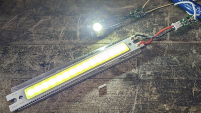
Here is a 1W Cree style LED and a COB running on the CULD:
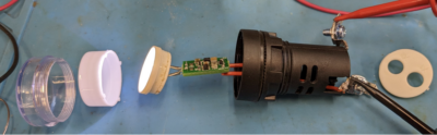
Remember that 24V LED panel indicator? Add a CULD and it will be the same brightness from 10 to 50V and draw less than ½ the current of the original:
How do is this universal?
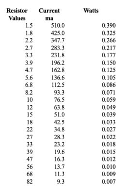
Besides the multitude of LED configurations you can set the current for the LEDs with a simple resistor R2. The LV2862 uses a 0.7656V reference to regulate, so the current limiting resistor drops 0.765V at the current you want. Here is table using standard resistor values showing what the current would be and the power dissipation of the current sense resistor:
How is this cheap?
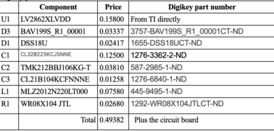
I originally tried to design a circuit board when I found the LV2862 and saw the quantity 1000 price I worked up the full parts cost at quantity 1000, Note the LV2862s are purchased directly from Texas Instruments
Digikey prices as of 6/9/2023
Where to go from here
It would make sense to find an input bridge rectifier that can handle the whole 600ma, cost is likely to go up a bit and if you want to keep the foot print small you can put the bridge on the back instead of extra LEDs. I have found some dual diodes that would work, but the cost per pair significantly higher than the existing solution, plus you need two of them. Four discrete diodes would work as well, again more cost and more components.
Smaller components
The component and board size was chosen mostly do to the needs of manual assembly, some components could be smaller like R1 and everything could be closer together or on both sides of the board.
Current sense resistor
Its possible to include some form of current adjust, a potentiometer (although power dissipation might be an issue) or multiple resistors with bridge/cut pads to select a value. But I think the easiest solution would be to design for a through hole resistor. You could even include a basic 39 ohm (20ma) surface mount resistor with holes to add a parallel resistor to get higher currents.
Don’t yell at me
My analog design skills are lacking, so its likely the component values I have chosen are not optimal, if anyone wants to model this better I would appreciate it.
In a perfect world
I am leaving this design open source, I would like to see someone with the automation and infrastructure to make and sell these. I would rather buy them than make more myself.
Notes:
- Bridge rectifier selection:
Priorities: Size, cost. All the standard bridge rectifiers I found were at least 0.25×0.18”, a significant portion of the final board. So I opted for a signal diode with 4 diodes per package. The one I selected is very small, cheap but only handles 100ma. Ideal for my applications where I’m running 36-48V to drive no more than 4 LEDs. A better options for full current at lower voltages might be a pair of RF051UA1D – $0.124 in quantity. You could go with a bridge and make the board larger or put it on the back of the board: MD2JS less than $0.10 in quantity. Or leave it off completely and gain back the 1.4V at low voltage inputs.
- Single Sided and multi LED
The design is single sided, this was great for making my own board, but when I had them manufactured I went with a double sided board. This allowed me to add pads for LEDs on the back side. Start with a single LED in parallel right behind the front surface mount LED – so its easy to have it light on both sided – mounting won’t matter. Then I added pads for 4 LEDs in series with spacing so you could have 1, 2, 3 or 4 surface mount LEDs on the back – See multi LED image above.
- Voltages
Minimum input voltage for the LV2862 is 4V, the sense resistor needs to drop 0.765V and the forward drop for the input diodes can be up to 2.5V for higher currents. With the bridge minimum input voltage is: VLED + 0.0765 + 2.5 (minimum 6.5V)


