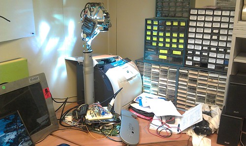
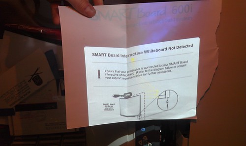
Back in August, Tom acquired several Smartboard-brand projectors and was interested in getting them to work as a normal projector would. As you may recall from my original post on this project, these projectors will not display anything other than an error screen without their accompanying interactive whiteboards connected.
The original approach was to simply substitute my own video signal by swapping out some cables. There is a dual-link DVI cable that attaches to the projector lamp assembly through the telescoping neck of the projector to its wall-mounted computer base, the Unifi 35. I tried simply connecting a computer to the DVI connection on the lamp, but the lamp wouldn’t power on. We eventually surmised that the lamp and the Unifi 35 were communicating somehow through the DVI cable and the lamp wouldn’t power on unless the computer detected that it was attached. Computers with DVI connections have the ability to detect when display devices are connected as well as instruct them to power on or off.
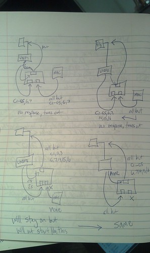
That led to trying to swap out individual pins in the cables. I built three DVI breakout boards and set up a breadboard so I could mix and match pins from two sources and combine them to send on to the projector lamp. I tried using the digital pins from my own source (a G5 Macintosh) and the analog pins from the Unifi 35. After a lot of trial and error, it seemed the projector was communicating with the Unifi 35 somehow using either the analog pins on the DVI connection, the second digital link, or both. Also, it seemed I could disconnect some pins after the projector was powered up, but I couldn’t start without them. It looked something like this (table copied from Wikipedia):
| Pin | Description | Purpose | Required? |
|---|---|---|---|
| 1 | TMDS data 2− | Digital red− (link 1) | Required at all times |
| 2 | TMDS data 2+ | Digital red+ (link 1) | Required at all times |
| 3 | TMDS data 2/4 shield | Required at all times? | |
| 4 | TMDS data 4− | Digital green− (link 2) | Required at all times? |
| 5 | TMDS data 4+ | Digital green+ (link 2) | Required at all times? |
| 6 | DDC clock | Required at startup only | |
| 7 | DDC data | Required at startup only | |
| 8 | Analog vertical sync | Required at startup only? | |
| 9 | TMDS data 1− | Digital green− (link 1) | Required at all times |
| 10 | TMDS data 1+ | Digital green+ (link 1) | Required at all times |
| 11 | TMDS data 1/3 shield | Required at all times? | |
| 12 | TMDS data 3- | Digital blue− (link 2) | Required at all times? |
| 13 | TMDS data 3+ | Digital blue+ (link 2) | Required at all times? |
| 14 | +5 V | Power for monitor when in standby | Not required? |
| 15 | Ground | Return for pin 14 and analog sync | Not required? |
| 16 | Hot plug detect | Not required? | |
| 17 | TMDS data 0− | Digital blue− (link 1) and digital sync | Required at all times |
| 18 | TMDS data 0+ | Digital blue+ (link 1) and digital sync | Required at all times |
| 19 | TMDS data 0/5 shield | Required at all times? | |
| 20 | TMDS data 5− | Digital red− (link 2) | Required at all times? |
| 21 | TMDS data 5+ | Digital red+ (link 2) | Required at all times? |
| 22 | TMDS clock shield | Required at all times? | |
| 23 | TMDS clock+ | Digital clock+ (links 1 and 2) | Required at all times? |
| 24 | TMDS clock− | Digital clock− (links 1 and 2) | Required at all times? |
| C1 | Analog red | Required at startup only | |
| C2 | Analog green | Required at startup only | |
| C3 | Analog blue | Required at startup only | |
| C4 | Analog horizontal sync | Required at startup only | |
| C5 | Analog ground | Return for R, G, and B signals | Required at startup only |
After a lot of trial and error, I didn’t seem to be much closer to the goal of getting my own video source to display. I also began to consider that the manufacturer may have switched around some pins between the Unifi 35 and the projector to prevent consumers from servicing the unit. The DVI cable I was working with was internal to the machine after all. There’s no reason any one would ever try to connect their computer’s DVI output to the lamp itself. Signals leaving the Unifi 35 could be sent on a different pin than the DVI standard suggests and then rearranged back into the standard configuration at the lamp assembly. I never really dismissed that possibility, but I also didn’t see much to support it.
I trudged on and hooked up an oscilloscope to monitor was was going on with the analog pins, C1 through C5, because they seemed to be critical to the lamp turning on, but not necessarily staying on. This is what I found:
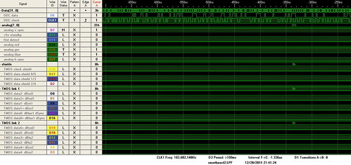
Unsure of what these signals represented, I consulted with Royce, Tom, and a few others and worked up the courage to use a logic analyzer for the first time. Most of the work was wiring the thing up and assigning names to the leads in the software. My breakout boards turned out to be more fragile than I expected so I ended up resoldering a all of the flaky connections. The Intronix 34-channel Logicport Analyzer is pretty slick and comes with some great software tutorials. Once I got it going, it was fairly straight forward. I can definitely see how this device can come in handy now that I’ve used it.
One of the first problems I ran into was the multitude of different voltages at work. The Logicport software has a logic voltage threshold setting to help weed out logic from other signals, but I found myself dealing with signals less than 0v, as well as +3.3v, and +5.0v. I eventually scanned the spectrum and sat, clicking the threshold up in small intervals of 0.05v, and watched to see if anything appeared on the screen. It would seem that while in standby mode, some of the the TMDS data pins and the DDC clock and data pins are held above +2.0v. Around 0.0v, some of the data shields show some variation between low and high during standby but as the projector is starting up, there are definite patterns on TMDS data shields 2/4, 0/5, and the clock shield. TMDS link 1 shows some activity during startup in the +3.3v range and then shortly after link 2 does as well as the analog red pin. Why a digital signal might appear on the analog pin is unclear. I could be measuring it wrong also, but there does appear to be a signal there. I also checked the analog pins during standby against what I saw with the oscilloscope and the numbers seem to agree except that the C4 horizontal analog sync pin showed voltage at or above +2.00v with the analyzer when the oscilloscope showed no voltage difference at all.
Since I was more interested in the control data than the video data, I focused my attention to the DDC clock and data pins to see if I could decipher how the projector and Unifi 35 were talking to each other. PC monitors and projectors with DVI connections use a display data channel (DDC) and a standard called I2C (I squared C). I found some great information on I2C and DDC protocols online here and here. At +5.00v I read a portion of the communication between the Unifi 35 and the projector and tried to analyze it. Unfortunately, the data doesn’t seem to follow what I’ve read on the I2C standard. The clock rises and falls unexpectedly, the start/stop commands don’t appear where I would expect them to, nothing resembles a 7-bit device address and there is seemingly no pattern to data. The other logic analyzer screenshots can be found here.
We considered trying to spoof the USB connection to the whiteboard at one point, but that seemed to be problematic also. I set up the logic analyzer and monitored the USB connection, but to no avail. It’s possible that without the board to receive power from the USB port, there’s no way of telling how the board would communicate with the Unifi 35 and projector. In a last ditch effort some weeks ago, I contacted Smart Technologies, makers of these products, and flat out asked them if the projectors could be used without the whiteboards. The answer was, unfortunately, no.
I began to lose interest after this and once I got back to the project after the holidays, I decided to finally give up on it. I would rather use my time on other projects. It was by no means a waste as I gained more experience etching my own circuit boards, soldering annoying small connections, and I got comfortable with the logic analyzer; assuming I used it right. I also became wary of computer cable vendors on Amazon.com. During the project I needed some dual-link DVI cables, but when my order showed up, the second data link pins (the six in the middle of the connector) weren’t even wired. I stuck a multimeter to them and found continuity on all but those six pins. Needless to say, I left them some grumpy feedback and got a refund. Thanks to everyone who helped and gave me advice. As Shane said, “I doubt anyone else would have gone this far.” I took that as a compliment.


