Ahoy, LOY!

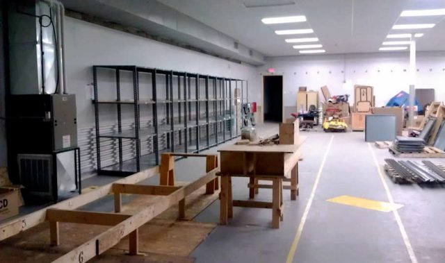
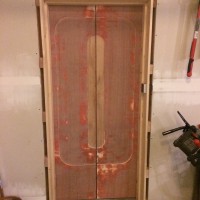
The photo above was taken in March of 2013, just two months after we moved into the building that is now home to Milwaukee Makerspace. Before January of 2013 we were located in the Chase Commerce Center, and Royce was the President, and Willie came to Royce with the idea of using the space to build a boat.

On the left side of the photo is the frame that Willie would build his boat upon. For the next (nearly) five years, anyone who came through the space for a tour, or showed up for an event, would at some point be told “And this where Willie is building a boat.”

Every week, or month, you’d see some progress. Willie would be working diligently on the boat. He thought it would be done in 2015, and then he thought it would be done in 2016, and finally, In August of 2017 the boat (named “LOY”) was ready…

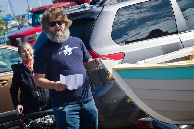
And on September 2nd, 2017 Willie, along with his family, and friends, and members of the space, celebrated, and launched the boat into Lake Michigan. It was a beautiful day, and I’m not just talking about the weather. It was the culmination of years of work, and a testament to what Milwaukee Makerspace can be.

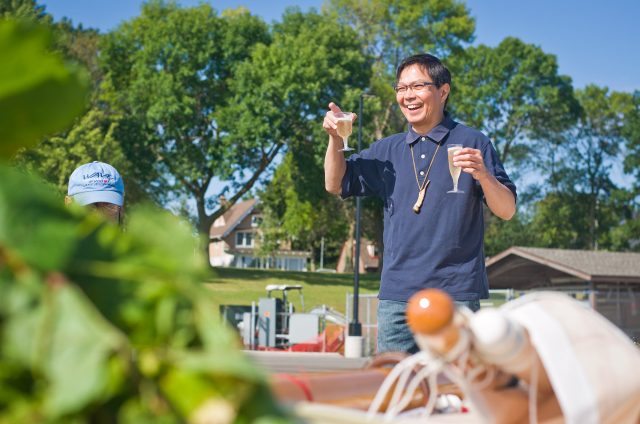
Royce, one of the Founders of Milwaukee Makerspace, said a few words about Willie, LOY, and the space. Royce doesn’t get to the space as often as he used to (kids, life, etc.) but it was great to see him talk about Willie and the boat, and how it all came together to happen at the space.

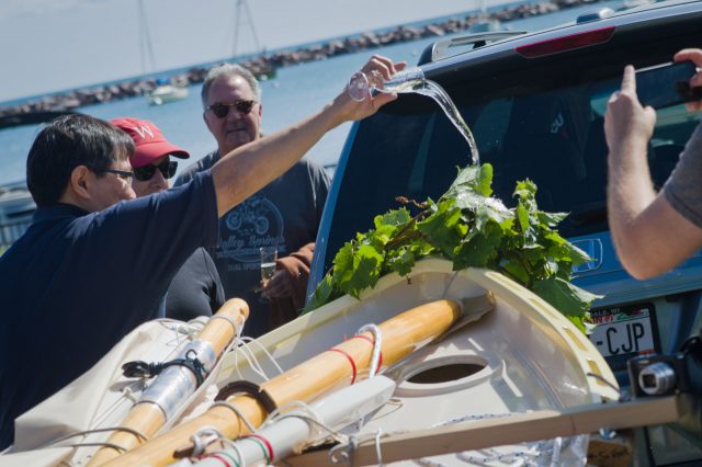
Willie pours champagne on the wreath at the bow of the boat. Much better than smashing a bottle against the hull!

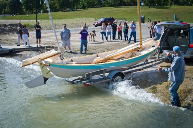
It’s nearly in the water! Wolfgang mans the lines and keeps things steady for the moment LOY touches the waters of Lake Michigan for the first time.

It floats! Willie made a joke that most boats only sink one time. He then got to work doing all the rigging necessary for a sailboat. There’s a lot of setup involved for the masts, sails, rudder, etc.

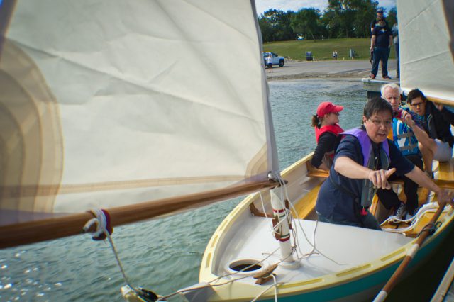
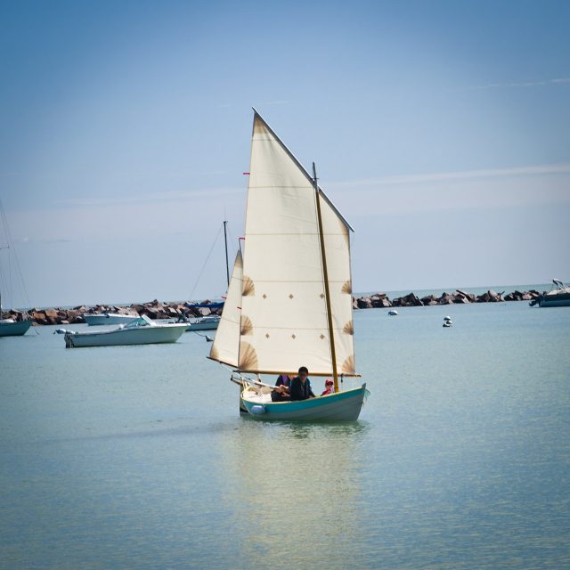
Captain Willie in command! Ready for the maiden voyage of LOY.

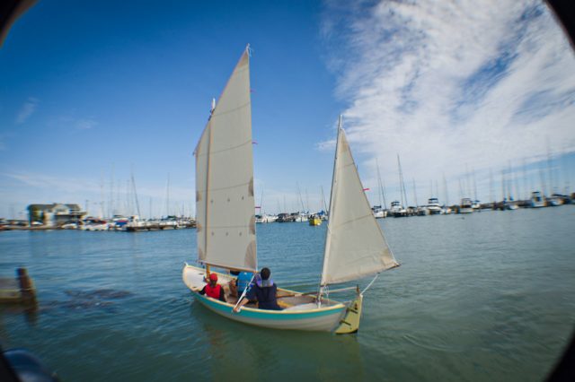
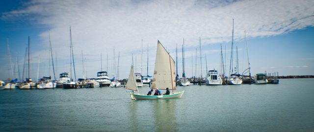
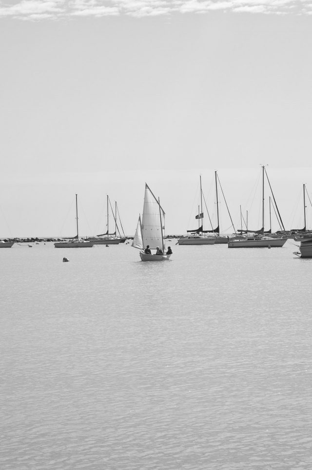
And they’re off! Seeing LOY sail away was an emotional experience. Many of our members know what it’s like to build large and complex projects, and some members know what it’s like to work on a project for years, but seeing that beautiful boat, and knowing all of the hours Willie put into it… it was something to behold.

Also, check out Carl’s video of the launch. It does a great job of compressing the morning into a few minutes, and hopefully you get a feel for the excitement of the day.

Finally, if you want to see LOY in person (and you should!) Willie will have his breathtaking creation at Maker Faire Milwaukee on September 23 & 24, 2017.

STAR TREK DOOR Continues

So, the STAR TREK DOOR has been a slow, “back-burner” project for a while. Recently, I got a little time, so I sat down and figured out how to hook up the air valves to a set of relays, and control those relays with an Arduino.

Here’s a video overview of the physical doors themselves and how we plan to open and close them with air valves.

This is a joint project, working on this with my brother-in-law, Fred. The doors are between his garage and workshop. Fred has been working on the doors themselves, the wall and framing, and mechanical connections. I’ve been working on figuring out the software, controls, and electronic magic that will drive everything.

IMG_6655IMG_6610
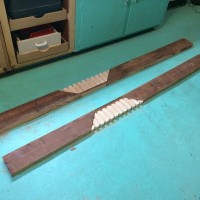
The physical doors themselves are done, except for paint. Fred has also been making a pretty neat frame for the garage side. He cut alternating widths of wood and then glued them together for the nice light-colored wood on the inset of the planks that will frame out either side of the door. A similar piece will cross the top of the door.

I got all the main components – Arduino, breadboard, relay board, 12V power fuse panel, and air valves themselves all screwed to a piece of plywood. At this point, it’s not pretty, but it is functional.

IMG_6652We have a nice industrial door control with OPEN/CLOSE/STOP buttons on it. Those are momentary on buttons, but through the power of the Arduino, I can make them be whatever I want. I started with a Button Tutorial, and then modified it to suit my purposes, and added a Delay(1500) command after activating the air valve. That way, the valve will stay open long enough to fully open or close the door, even if the button is just pressed for a moment.

I programmed the pin for the STOP button to test out a sequence to open the door, pause (long enough for a person to walk though,) and then close the door. It seemed to work pretty well. If the timing is wrong for the real-world application, all I have to do is simply change the delay times. (It will also need a safety. We don’t want the door closing on a person!)

IMG_6520At this point, the basics of the control panel are working. The STOP button is just wired up as a “stand-in” for a single button we already have installed on the garage side of the door. It’s a capacitive touch button that lights up either blue or white with internal LEDs. It’s a neat looking button, but it’s only a SINGLE button. So, it needs to have functionality to both open AND close the door. I’d also like to explore using a variable in the Arduino that states whether or not the door is open, and then changes the functionality of that button based on whether the door is open or not. The air cylinders themselves also have built-in position sensors, which would be neat to use possibly as both a safety AND a “Is the door open or not?” sensor.

Here’s a video clip showing all the components actually working together. At this point, if the panel was simply mounted above the door, and air connected between the compressor and air cylinders, we would actually have functioning doors.

IMG_6653I don’t like the look of how the air valves and tees are held together right now. I was able to find some not-too-expensive push connectors (similar to PEX Sharkbite style) for air, which might make it a little easier to connect all the air components and look cleaner. Once I really have everything finalized on what’s going on at the breadboard, I also need to decide if I want to pull the breadboard out and replace it with a custom circuit  board. One thing I DO need is a simple way to connect the tiny pin connectors to the larger wires going to the buttons AND provide strain relief. For the moment, I just used staples to nail the 18 ga lamp cord wire to the plywood and then made the electric connection with alligator clips. What would be the BEST/CLEANEST way to do this? Some sort of small screw down terminals?

I also have a rather large fuse panel mounted on the plywood. It was free, and I already had it. It supports many separate circuits, but for this project, a single DC fuse would probably be fine. I’m also using a bit of an overkill 12V power supply. I’ll want to replace that with a simple wall-wart. Lastly, the Arduino is running from USB power. I’ll need to solder up a 12V DC barrel connector so that it can run off the same power as everything else. I think we will make a switched electric outlet, and plug the wall-wart in to that. If the system is ever not working right, just switch off the power and manually open and close the door as needed.

I’ll definitely want to hang out with the guys at the Makerspace sometime soon talking Arduino, specifically how to integrate some more sensors and get feedback used to activate the doors fully automatically.

-Ben Nelson

QWERTY (and nothing else)

QWERTY Keyboard

I built a QWERTY keyboard that types the letters Q, W, E, R, T and Y, and nothing else. No space, no return, no escape.

It’s a fully-functional USB device, you know, as long as you just want to type words that can be composed with Q, W, E, R, T and Y. (WET, WRY, YET, TRY, there’s a bunch of them!)

I wrote plenty more about this project on my blog, and if you want to read about the history of the QWERTY layout, and its connection to Milwaukee, and why the way we interact with technology is interesting and sometime ridiculous, well… I got that too.

Square(ish) Pegs

Laser-Cut Pegs

Often laser cut parts get attached at 90 degree angles, using finger joints, or screws and t-slots, but there may be times when you want to stack pieces of wood and have them aligned…

Pegs might be the answer!

Here’s a few photos of the pegs I’ve been experimenting with. For these pieces I don’t have a lot of room to have multiple pegs at opposing angles, but I can see where that might be useful. For these pieces the peg is really just for assembly alignment when gluing it all together.

Laser-Cut Pegs

Weekend Project: Wine Rack

Last weekend I made a 60 bottle wine rack from some 1″ pine.  I sized it to fit on a counter top in my basement, under the upper cabinets. I was pretty happy with the design of a somewhat smaller Belgian beer rack I made in the past, so I copied some of its basic style. I really like the strong vertical lines of this design, as it contrasts with the strong horizontals of most wine racks.Wine_Rack_Assembled4

With the compound miter saw and table saw, I transformed three 6′ long pine 1″ x 12″ boards into the necessary 150 pieces! The rack holds 60 bottles, so I cut 120 10″ x 9/16″ x 3/4″ pieces. These are connected to 26 uprights that measure 18.1″ x 3/4″ x 1.5″, which are connected to 4 horizontals that are 52″ x 3/4″ x 1.5″.  Note that a spacing of 3.1″ is sufficient for wine bottles, but 3.35″ is the minimum for most champagne bottles.  The 3.35″ width also holds half bottles and just barely holds 12 oz beer bottles.  Also note that for strength reasons, the 10″ long pieces need to be cut along the grain, not across it.  Here are all the pieces, just before I nailed them together:

Wine_Rack_Parts2

It took about 1.5 hours to cut the pieces, and 1.5 hours to assemble them. Note that I used a nail gun and 1″ long, 18 gauge nails for most connections, except the uprights to horizontals, where I used 2″ long nails.  Check out the completed wine rack, made from $25 of wood and nails, in use!

Wine_Rack_Full2