The mold and final cast part.
As someone who has gone to GenCon quite a few years and knows several of the GMs of major events, I’ve started getting asked to make props… This year I have decided to expand my experiences in molding and casting in order to make one of the props. The prop requested was a “Bracer that looks like it is made of Amber – part of the shell of an insect”. Thankfully I was afforded quite a bit of creative leeway beyond that.
In the past I have used Smooth-on products, but one of the members of the Makerspace mentioned they were a distributor for Alumilite, so I thought I would give them a try. This was my first experience with most of the Alumilite products.
I ordered the following supplies:
UMR 12 oz.
Alumilite Dye 1 oz. Red
Alumilite Dye 1 oz. Yellow
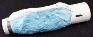
Mold Putty – 15 2 lb. Lt. Blue
Amazing Clear Cast 2 gal. Kit Clear
Synthetic Clay
Other items I used:
A form made out of a 3″ PVC pipe shaped to look like a human arm.
3” Diameter PVC Pipe – Approximately 18” long
3” Diameter Hose Clamp
Plaster Bandages
Vaseline
Disposable Mixing Containers
Stir Sticks
Steel Wire (to hold the mold together)
Syringe
Drinking Straw
I wanted to make a “generic” bracer that would fit either arm, not a right or left arm bracer, so I didn’t want to do a life cast of my arm first – it would be too specific. Instead I picked up a piece of 3” pvc pipe, cut a section out of most of it (leaving a part connected) and then used a hose clamp to tighten the open end down. It turned into a really good stand-in for a human arm. The shape is close enough that it is recognizable, but is not left or right arm specific. (Note that the screws in the picture were added at a later stage)
Once I had the basic form for the arm, I used the synthetic clay to create the shape of the bracer. I was going for an organic look, so I wanted curves and no sharp edges. The biggest challenge I had was trying to smooth out the sculpt. I still need to figure out the right technique. Sadly, I forgot to take pictures of the sculpted bracer.

The form and original covered with mold putty.
Once I had the sculpture complete, I added some screws around the edges as alignment points. I was careful to make sure the heads were close to the PVC so they would not get stuck in the molding material. Then I got to try my first new material – the Mold Putty. I really liked the idea of it – take two parts, hand-mix, then just push it onto the original. It essentially worked exactly that way. I thought the mixed consistency was almost perfect for my application. Unfortunately, the biggest difficulty is being sure not to trap air in it – particularly when placing a second mixed batch next to an already placed batch. I ended up with some imperfections in the final mold because of this. Would I use it again? Yes, but I think I may also try other approaches – either a box and pourable rubber, or brush-on rubber.
The mold with half of the mother mold present.
Given the way I wanted to cast the bracer – standing vertically – I wanted to make sure that I was able to hold the rubber mold to the arm form well. So, using the plaster bandages, I made a two-part “mother mold” for the rubber mold. First, I coated everything with Vaseline as a release agent, then I covered half of the arm piece with plaster bandaging, making sure the edges were particularly strong, and that the top edge, where I would be creating the second half of the mold, was also quite smooth. After the first half of the mother mold cured, I then coated the edge of the plaster with Vaseline to make sure the other half would not stick to the first half. Once I was done placing the Vaseline, I then coated the other half with plaster bandages.
Once all of the plaster dried, I used a sharpie and drew lines across the edges of the plaster. These lines are so that I could realign them easily after I took the mold apart to remove the original sculpt.
After I removed the original sculpt, I realized I forgot something major… A way to get the resin into the mold. Oops! After a bit of thought, I decided the easiest way to get the resin in would be to drill some holes through the PVC pipe and pour it in that way. Ideally, I would have designed pour holes and vent holes into the original design of the sculpt. Something to remember for the next one! In order to try to control the fluid a bit better, I used straws to extend the holes out. Bendy straws would have been good – I’m not sure how effective straight straws were.
Using the volume of clay from the original sculpt, I did a rough guess at how much resin would be needed to fill the mold (~12oz). I measured out 6oz of each of the two parts, added one drop of red and six drops of yellow to one of them, then mixed it. I used a syringe to suck up the mixed resin and transfer it into the mold. It worked quite well, although it was a bit disconcerting because of the number of bubbles that were exposed during the suction process. Thankfully, as soon as the resin reached normal pressure the bubbles disappeared.
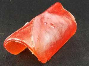
The raw bracer prop as removed from the mold.
The resin takes 24 hours to cure. 24 hours wondering if it turned out.
And after that full day of waiting, I de-molded it. Quite the pleasant surprise! I think it may have slightly too much red, so I’ll have to correct that for my next iteration. I’m still debating about sanding and buffing it in order to get it to be more glass-like.
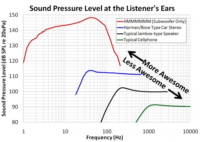 The plot shows how loud typical audio systems are, and how low they play. For example, cellphone speakers play only a bit below 1khz, and are ~90 dB if they’re 40cm from you. When a Jambox-type bluetooth speaker is about 60cm from you, it plays ~10 dB louder, and another 1.5 octaves lower, to 200 Hz. Typical bookshelf speakers can get another 5 dB louder if you’re 1.5 meters from them, but only play down another octave to 100 Hz. OEM installed car stereos are a big improvement, but they’re still not in the same league as the HMMMMMM. Yes, the