Random Find: The Avago/HP HDLG-2416

Anyone who’s ever visited Makerspace knows that the ‘Library’ is home to tons and tons of stuff.  Component parts, IC chips, belts, pulleys, batteries, etc.  Occasionally I lose myself in there for a few hours and just explore the shelves.  This is a post about one of my more interesting discoveries.
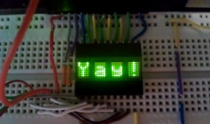

I came across a whole bag of these in the LED bins.  They’re 1″ wide, four-digit alphanumeric displays.  Each character consists of a 5 mm tall, 5×7 LED dot matrix display.  The device comes complete with on-board RAM and an ASCII decoder capable of displaying up to 128 different characters.  It’s even possible to dim the brightness.  I’m also partial to the color green.

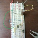
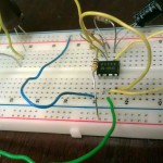
The major drawback I’ve found is the number of pins required for use.  The thing has seven data pins and the extended features for writing/reading/displaying require a ton of connections.  I used all but four of my Arduino Uno’s I/O pins while tinkering with it.  You’re probably better off using a LCD display or something with serial data support, but these are still small and numerous in our ‘Space so they’re worth toying with.  Also there’s been a few other people who played with these and posted their findings online. I’m seriously considering building a small desk clock around one or two of these in the future.

If you’re interested in using one of these displays on your next project, I’d suggest reading the blogs by these fine folks here:

http://buzzdavidson.com/?p=148

http://dorkbotpdx.org/blog/wardcunningham/yow_revisited_in_txtzyme

http://gorgusgfx.se/?page_id=62 (I think this is in Swedish, but the code still works!)
 

Magic Mirror Theater Prop

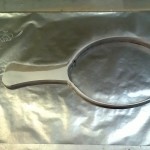
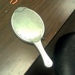
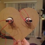
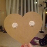
My sister is a Theater Manager at the Patel Conservatory in Tampa, FL.  About two weeks ago she texted me and asked if I could make her a prop she needed for an upcoming production.  “How keen would you be on making me a mirror for “Beauty and The Beast,” she said.  “They want a mirror that lights up and sparkles like the one from the movie.” Even with limited experience just tinkering around, I knew I could do something fairly easily, so I agreed and got to work.

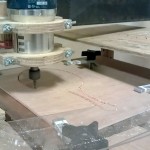
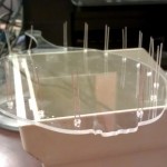
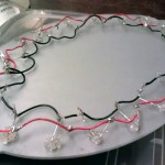
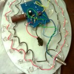
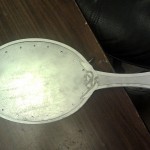
I combined two different circuits (a 555 timer to flash and a RC circuit to fade) and built a wooden frame with acrylic plates for the front and back.  The wood and plastic were CNC-milled, then sanded and painted before the electronics were installed and glued into place.

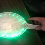
The result was a fairly decent-looking, shiny, light-up hand mirror with a small thumb button on the right side that flashes 16 bright green LEDs when pressed.  It all runs off a single 9-volt battery and the back can be unscrewed to replace it should it ever die.

Total build time from start to finish was probably close to 15 hours over the course of one week.  The play was Thursday, July 19th and from what I’ve heard, it was a great success.  I’ll add pictures from the performance if I get some.

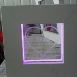
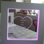
Wedding LED Unity Display

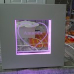
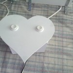
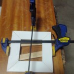
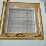
I’m getting married in less than a week from now. My fiance and I didn’t want to use a traditional unity candle for our ceremony, so I came up with something a little different. I used some RGB LED strips to create my own LED unity display.


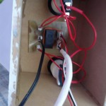
The LEDs are controlled by a relay and two arcade buttons wired in series. When both arcade buttons are pushed the LEDs in the two smaller frames are are turned off and the LEDs in the large frame are turned on.


Completing this project required using the laser cutter, the CNC router, making my own PCB, and even a little bit of wood working to put the frames together.


A Simple Aux Input For iPod Speaker Systems

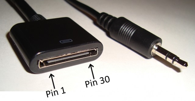
The first generation of Bose SoundDocks did not feature an aux input jack, they are only compatible with the 30 pin connector of iPods and iPhones.  Lately, my music player of choice is my Droid Razr, which has 60+ Gb of music on it, even more in the cloud, and no 30 pin connector.  I decided to add an auxiliary input to my SoundDock in the easiest and quickest way possible. I made an adapter cable using half of a $6 iPod extension cable, half of a $1 3.5mm headphone cable, and two necessary resistors.  I can plug this adapter cable directly into any unmodified SoundDock, or any other amplified speaker system that has a 30 pin connector.

It turns out that the SoundDock is smart, and will only power on when it senses 3.3VDC on pin 18 of its input connector.  Luckily, it also outputs 12VDC on pin 19 to recharge the attached iPod’s battery.  To trick the SoundDock into turning on with no iPod attached, I made a voltage divider by soldering a 20 Kohm resistor between the wires connected to pins 18 and 19, and a 4.7 Kohm resistor between the wires connected to pins 18 and 1.  The voltage between pins 18 and 1 was measured to be ~3VDC, which isn’t 3.3VDC, but is sufficient to power up the SoundDock.  I soldered the three pins of the 3.5mm headphone jack to the 30 pin connector’s wires as follows: Ground to pin 1, right audio to pin 3 and left audio to pin 4.  I used 1206 surface mount resistors because they measure only 3.2mm by 1.6mm, a size which fits conveniently under the shrink wrap joining the two cables.  The most time consuming part of this two hour project was identifying which color wires were connected to pins 1,3,4,18 & 19, and determining if the pin on the left of the photo was #1 or #30.

Makers, assemble!

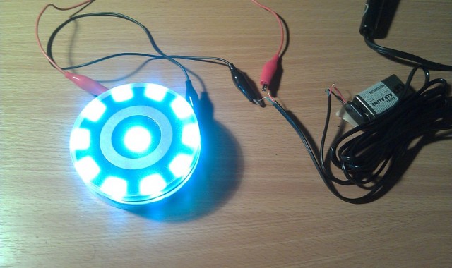
Yeah.  Having access to a laser cutter is pretty boss.  I’m planning to wear this to the premiere of a certain movie this weekend.  Four layers of acrylic; two diffuse, two opaque.  11 LEDs, 11 100 Ohm resistors, some phone cord, some solder, and a 9V battery.  There’s no lack of great pages on Instructables about how to make your own.